I wish I could say yes.. I still have to finish populating the second Q-Watt. Transformers will arrive this week. Need to finalise PCB mounting arrangement on the heatsink and drill a few more holes. Then... if the soft start still works with 2x 420VA toroids then it's just a case of testing and tuning the PCB and then wiring up neatly. Not far to go. Pops.
I wish I could say yes.. I still have to finish populating the second Q-Watt. Transformers will arrive this week. Need to finalise PCB mounting arrangement on the heatsink and drill a few more holes. Then... if the soft start still works with 2x 420VA toroids then it's just a case of testing and tuning the PCB and then wiring up neatly. Not far to go. Pops.
Yeah it sure is a lot of work.
Myself, I (almost) completed my second channel yesterday. It is up and running but the enclosure is not completely finished yet.
... but I diverted from my initial design... Seeing yours and Caple's enclosure I fell in love with the mini disipante 🙂 So, my second channel is built into a 2U 250mm silver Mini Disipante. I did have to make some modifications to the way the enclosure is put together. There where some brackets "in my way" for proper construction. I'm now waiting for the backpanel that I designed with Front Panel Designer from Shaeffer.
I'll post some pictures when its finished.
Next on the agenda is to convert the first channel into a Mini Disipante enclosure. That should keep me busy for a while 🙂
Looks good popchops.
Did you sort out your power supply?
Yep. I'm not going to change much. New transformers will give about 55V @ 240V. No inductors, no resistors.
I will probably fit off-the shelf RC snubbers across the secondary terminals at the bridge rectifier, and same across the filter caps when I get some time in the lab.
Might twist the wiring between the rectifiers and the 1st filter cap. What do you think?
Pops.
Attachments
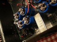
definitely twist your wiring............Might twist the wiring between the rectifiers and the 1st filter cap. What do you think? ................
Every LOOP acts as an aerial, transmittting and receiving interference.
See the two parallel copper wires running between your capacitors. They are forming loop with big areas. They are emitting emi every time the current changes.
Thanks Andrew.Every LOOP acts as an aerial, transmittting and receiving interference.
See the two parallel copper wires running between your capacitors. They are forming loop with big areas.
Cool - I might try designing a slick backpanel with labels once the beast is up and running. I don't need any more distractions!!I'm now waiting for the backpanel that I designed with Front Panel Designer from Shaeffer.
Glad you like the Mini Dissipante - am a bit miffed about a couple of things:
- rubbish feet. Really nasty.
- the solid spines of the heatsinks are only 7.5mm thick/deep. For 40mm fins I guess I expected 10mm base, from looking at other standard heatsinks. Hifi2000 have gone cheap there. Should do the job though.
Pops.
Last edited:
Glad you like the Mini Dissipante - am a bit miffed about a couple of things:
- rubbish feet. Really nasty.
- the solid spines of the heatsinks are only 7.5mm thick/deep. For 40mm fins I guess I expected 10mm base, from looking at other standard heatsinks. Hifi2000 have gone cheap there. Should do the job though.
Yes those rubber feed are cheap but I personally don't mind them. They do a good job keeping the enclosure steady on a surface. The feed are also quite invisible underneath the enclosure and I like that.
The base of my headsinks are 8 mm. I drilled some (threaded) holes in there because they now hold my base plate. I don't use those metallic strips at the bottom because they take up to much useful space.
My amp has been running the whole day yesterday and the heatsinks don't get hot; they do seem to work very well in terms of heat dissipation. I'm using a 2 unit high (8 cm) enclosure and they are fine for the Q-Watt.
I don't like the way they mount the front and back panels though. I didn't change the front panel but I will mount the back panel in the heatsinks as well. I've make my back panel plates are a bit lager to make that possible.
As you will see when I put up some pictures, the front panel is very difficult to mount when there is not a lot of free space inside the enclosure...
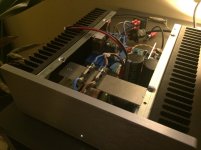
Other than that, I'm very pleased with the mini disipante. It is a very nice looking enclosure. I attached one crappy foto as a teaser 🙂
Attachments
Myself, I (almost) completed my second channel yesterday. It is up and running but the enclosure is not completely finished yet.
... but I diverted from my initial design... Seeing yours and Caple's enclosure I fell in love with the mini disipante 🙂 So, my second channel is built into a 2U 250mm silver Mini Disipante. ...
Next on the agenda is to convert the first channel into a Mini Disipante enclosure. That should keep me busy for a while 🙂
Delange,
and I've been falling in love with the design of the eclosures you created 😉. I'm still in search of suitable heatsinks for enclosures like yours'.
In my opinion it is a waste of a pretious (and expensive!) heatsink if only one power amplifer channel is put into a Dissipante enclosure. Maybe it's possible to use an 3U Mini Dissipante and stack two channels with two SMPS into it?
Best regards!
Maybe it's possible to use an 3U Mini Dissipante and stack two channels with two SMPS into it?
This is similar to Calpe's configuration I think. I also am using 3U x 300mm heatsinks, one each side per Q-Watt.
Pops.
Last edited:
In my opinion it is a waste of a pretious (and expensive!) heatsink if only one power amplifer channel is put into a Dissipante enclosure.
Yes, these enclosures are not so cheap, especially if you need two of them.
Maybe it's possible to use an 3U Mini Dissipante and stack two channels with two SMPS into it?
Maybe is possible to mount 2 complete amps inside a 3U enclosure. I didn't try because I need two mono blocks (2 separate enclosures) for my use case. Also, I don't like "large" enclosures but that is a personal thing.
I would like to use a Takachi enclosure next time. Maybe HY Series.
ALMINIUM ENCLOSURE | TAKACHI ENCLOSURE
Expensive and heatsinks are not enormous (not really big enough for Q-Watt at max dissipation) but quality looks fantastic.
Pops.
ALMINIUM ENCLOSURE | TAKACHI ENCLOSURE
Expensive and heatsinks are not enormous (not really big enough for Q-Watt at max dissipation) but quality looks fantastic.
Pops.
Aaaargh help!
I just wound the Q-Watt inductor (L1) anticlockwise instead of as shown in the Elektor photo.
Does it matter?
Thanks
Popchops.
I just wound the Q-Watt inductor (L1) anticlockwise instead of as shown in the Elektor photo.
Does it matter?
Thanks
Popchops.
Q-Watt finished
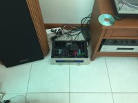
After long time to build this amplifier is now completed.
I have two old amplifiers, one to old, an hotchpotch from a Marantz model 32 it was build in a case from Marantz model 250 (long time ago I have serviced Marantz in the Netherlands)
The second model was also a Marantz model SM-6 with a burned out voltage amp.
Initially I had planned to use the SM-6 to build in this the Q-Watt, but I changed my mind and use the 32/250 as case and use also the transformer from the model 32.
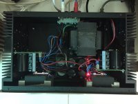
Unfortenately the transformer gives a lower voltage, with as result after rectification an 2x41V.
But in practice it appears to be sufficient, and with 8 ohm load I got appr. 20V
I have not gone higher because dissipation was quickly high.
And after listen to the amp today, I'm pretty happy, and yes the specs are real, THD checked with Keitly 2015 in accordance with Elektor.
After long time to build this amplifier is now completed.
I have two old amplifiers, one to old, an hotchpotch from a Marantz model 32 it was build in a case from Marantz model 250 (long time ago I have serviced Marantz in the Netherlands)
The second model was also a Marantz model SM-6 with a burned out voltage amp.
Initially I had planned to use the SM-6 to build in this the Q-Watt, but I changed my mind and use the 32/250 as case and use also the transformer from the model 32.
Unfortenately the transformer gives a lower voltage, with as result after rectification an 2x41V.
But in practice it appears to be sufficient, and with 8 ohm load I got appr. 20V
I have not gone higher because dissipation was quickly high.
And after listen to the amp today, I'm pretty happy, and yes the specs are real, THD checked with Keitly 2015 in accordance with Elektor.
Attachments

Aaaargh help!
I just wound the Q-Watt inductor (L1) anticlockwise instead of as shown in the Elektor photo.
Does it matter?
Thanks
Popchops.
You live in the UK right? Although you guys drive on the wrong side of the road it looks like it works ok for you 😀
Same goes for your inductor; will work fine.
After long time to build this amplifier is now completed.
I have two old amplifiers, one to old, an hotchpotch from a Marantz model 32 it was build in a case from Marantz model 250 (long time ago I have serviced Marantz in the Netherlands)
The second model was also a Marantz model SM-6 with a burned out voltage amp.
Initially I had planned to use the SM-6 to build in this the Q-Watt, but I changed my mind and use the 32/250 as case and use also the transformer from the model 32.
Unfortenately the transformer gives a lower voltage, with as result after rectification an 2x41V.
But in practice it appears to be sufficient, and with 8 ohm load I got appr. 20V
I have not gone higher because dissipation was quickly high.
And after listen to the amp today, I'm pretty happy, and yes the specs are real, THD checked with Keitly 2015 in accordance with Elektor.
Cool. Do the VU's work as well?
Thanks, unfortenately for long time they are defect, I've tried to repair with a cheap meter from China, but it is not possible to use that stuff.😡Cool. Do the VU's work as well?
I only place led's in the meters.
- Home
- Amplifiers
- Chip Amps
- My Q-Watt project