The insulators that came with the Elektor kit are ok in both regards. I used them as well and I would advice you to use those too.
Thanks Delange. Do you use 1 thin layer of thermal paste on the surface of the heatsink? Not on the semiconductors? Cheers - Pops.
totally agree with delange's views & suggestions.
popchops, add a small amount of heatsink compound on the I.C. to enable the heat to transfer to its heatsink.
I think i'll be placing Thermal Insulators inbetween the coil & heatsink, its too close for my liking.
I had to shave off 1-2 mm from the bottom of the heatsink close to R5.
Elektor states: -
"Start by attaching a heatsink plate, consisting of a piece of 2-mm aluminum sheet metal measuring 2.5 x 8 mm, to the IC with a pair of screws and nuts. Mount the heatsink so that it is a bit above the board when the IC is fitted, to avoid contact with R1, R4 and R5. Caution: the metallic rear surface of the IC is connected to the negative supply voltage. This means that if you do not use insulated mounting hardware, the heatsink will be at the negative supply voltage. For safety, we recommend using insulating mounting hardware here. Then solder the IC to the PCB. Just enough space for the heatsink has been kept free on the board (see Figure 5). Bend L1 slightly away from the heatsink".
After mounting all the transistors on the heatsinks, check to ensure there is no continuity from any of the transistor legs to the heatsink.
Good luck popchops
delange, should i connect the earth cable from the rear connection (see image in post 283) direct to the SMPS's or connect the SMPS earth connection to the bottom plate close to the SMPS input connection?
Last edited:
Connect the bottom plate to PE by a dedicated lead. Don't rely on the mounting screws only! Then you can ground the PSUs via short leads to the plate.
Best regards!
Best regards!
Connect the bottom plate to PE by a dedicated lead. Don't rely on the mounting screws only! Then you can ground the PSUs via short leads to the plate.
Best regards!
Kay, sorry but PE is?
Thanks Calpe.I think i'll be placing Thermal Insulators inbetween the coil & heatsink, its too close for my liking.
The coil is already insulted by its enamel coating but I guess anything that can touch can rub the coating off. Having scraped enamel off before soldering it seems damn tough though. Better to cautious.
Connect the bottom plate to PE by a dedicated lead. Don't rely on the mounting screws only! Then you can ground the PSUs via short leads to the plate.
Best regards!
Totally agree.
In fact, it is a requirement by law to connect the metal plates to PE and not to rely on screws and such to connect PE.
I also connected the SMPS PE terminal to PE with another dedicated wire.
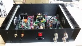
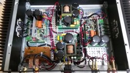
My Q-Watt as of 16th March 2017
Nice !
And did you fire them up?
(I would start them up one by one)
Thanks Delange. Do you use 1 thin layer of thermal paste on the surface of the heatsink? Not on the semiconductors? Cheers - Pops.
I treated both sides.
Same here!
And just another point: I've been somewhat astonished that people who construct mains powered gear don't even know the acronym PE, which is a very common one (more common than most abbreviations that are customary here within this forum 😀).
Best regards!
And just another point: I've been somewhat astonished that people who construct mains powered gear don't even know the acronym PE, which is a very common one (more common than most abbreviations that are customary here within this forum 😀).
Best regards!
Last edited:
Thanks for that. The earth connections on the amp are now actually wired as follows: -
Earth pin on Mains input socket connected to rear panel.
Rear panel connected to bottom plate.
From each SMPS mains input sockets earth, wired direct to bottom plate.
All i have left to do now is to wire from the mains switch to each SMPS mains input connection and double check wiring and transistor insulation (2nd time) on the heatsinks.
If the smps are not fused already, then add a fuse into the line feeding each SMPS.
There is usually a label indicating what fuse value to use.
There is usually a label indicating what fuse value to use.
Another basic question exposing my ignorance: when setting the quiescent current, I know I need to short out the input so the amp has no stimulus. Can I leave the output disconnected? Surely it doesn't matter if the binding posts are connected if there are no speakers plugged in.
Do I need a ground loop breaker on each PS connection (filter cap output) to the chassis?
I guess my bigger question is: should I treat the 1mm steel baseplate as a 'star' node and connect everything to it (albeit at different locations)? Thx, Pops.
I guess my bigger question is: should I treat the 1mm steel baseplate as a 'star' node and connect everything to it (albeit at different locations)? Thx, Pops.
If the smps are not fused already, then add a fuse into the line feeding each SMPS.
There is usually a label indicating what fuse value to use.
Each SMPS already has a 10 amp fuse on the live input.
popchops, as you have the same case as i do, what ive done is to connect the earth from the mains input to the rear panel.
Then from the rear panel (same connection point) i've taken an earth coloured cable (yellow with green line) and connected it to the bottom plate.
From my two SMPS's i then connected individually from their earth connection to the bottom plate, using only one connection point.
Then from the rear panel (same connection point) i've taken an earth coloured cable (yellow with green line) and connected it to the bottom plate.
From my two SMPS's i then connected individually from their earth connection to the bottom plate, using only one connection point.
the output should ONLY have the NFB connected. There must be no other load.Another basic question exposing my ignorance: when setting the quiescent current, I know I need to short out the input so the amp has no stimulus. Can I leave the output disconnected? Surely it doesn't matter if the binding posts are connected if there are no speakers plugged in.
If there is a small output offset and you also have a load connected then the load will draw a small current. That small (or not so small) current will affect the bias voltages across the emitter resistors.
Except for the tiny current that passes into the NFB, the upper and lower emitter resistors have an identical current.
If you have selected well matched emitter resistors, then you will find that the voltages also match.
If have 2pair then the sum of the upper exactly equals the sum of the lower.
The differencebetween the upper resistors is an indication of how well you have selected your matched pair. Similarly the lower resistor voltages indicate the selection quality of your lower pair.
- Home
- Amplifiers
- Chip Amps
- My Q-Watt project