Delete the zeners and 3.3k 1W resistors (ref. IRAUDAMP7S schematic) when injecting seperate regulated power supply. That should be obvious.
The zeners are internal to the irs2092.
This means any external voltage regulator should be 6 volts or less or it will blow up the 2092.
Member
Joined 2003
First, I was talking of Z103, Z104 on IRAUDAMP7S schematic. They are external to the chip, and would be the on-board voltage regulation provided you don't supply something different. Second, you can apply up to 210V to Vaa pin as per the datasheet.The zeners are internal to the irs2092.
This means any external voltage regulator should be 6 volts or less or it will blow up the 2092.
An externally hosted image should be here but it was not working when we last tested it.
Last edited:
Well, thank you for answers, do you have any examples schematics with regulator replaced zeners ?
Hi respected! L25D ordered 2 pieces last year. but the project was abandoned indefinitely. some free time, got the same to his L25D. read the whole forum almost unreal, standing in front of the power supply mode. please tell me which is better: a classic power transformer or SMPS based power from connexelectronic? variant in the price about the same.accept any help on this issue.
Regards,Nik.
Regards,Nik.
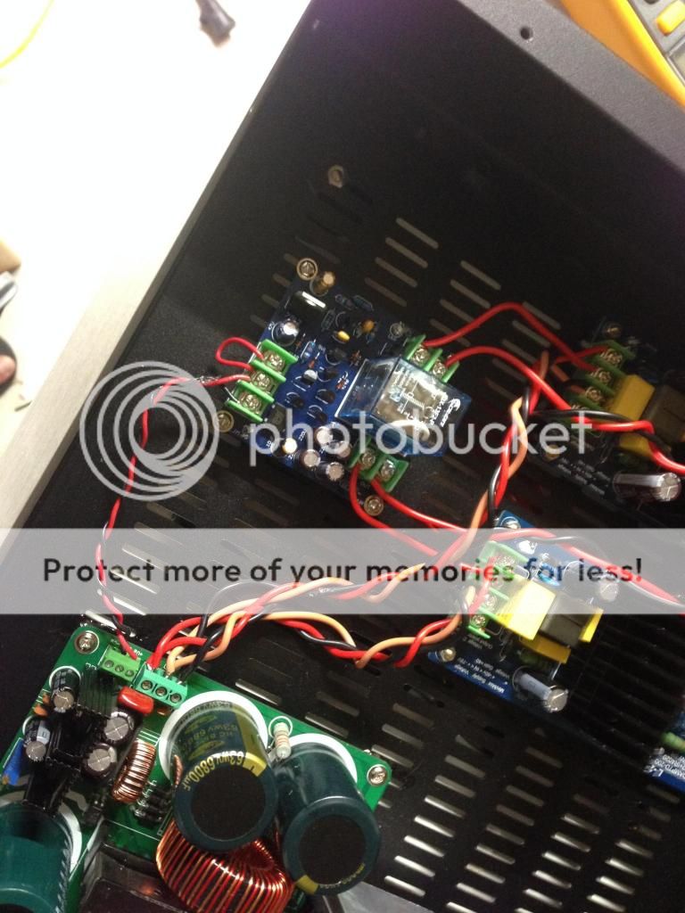
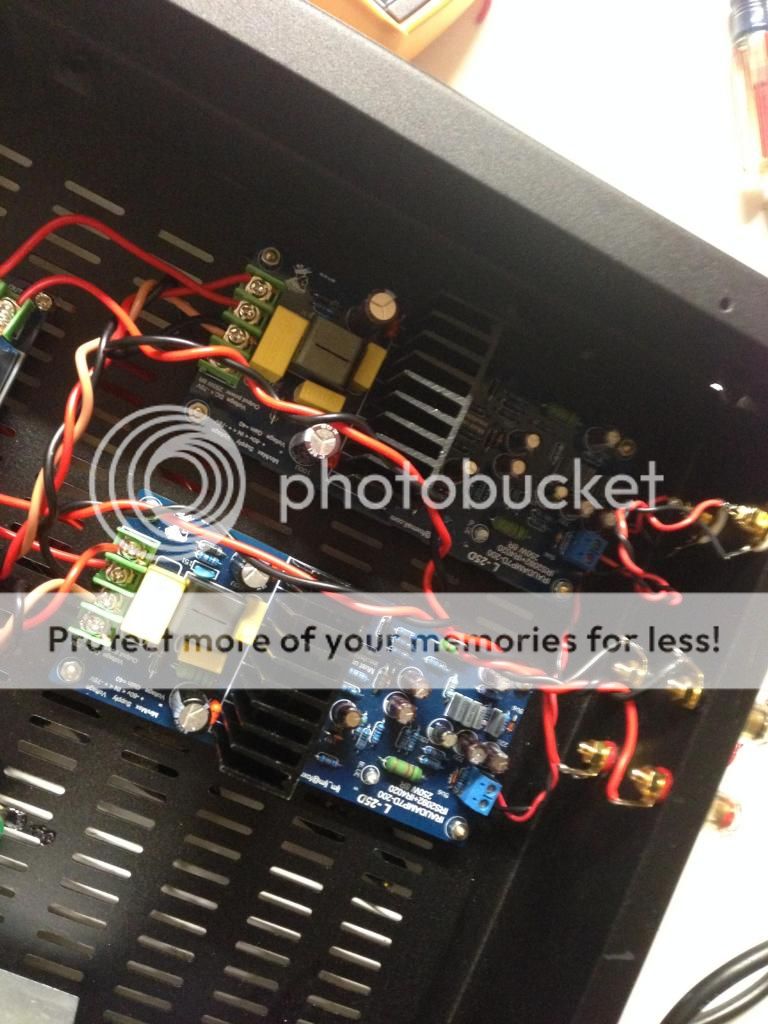
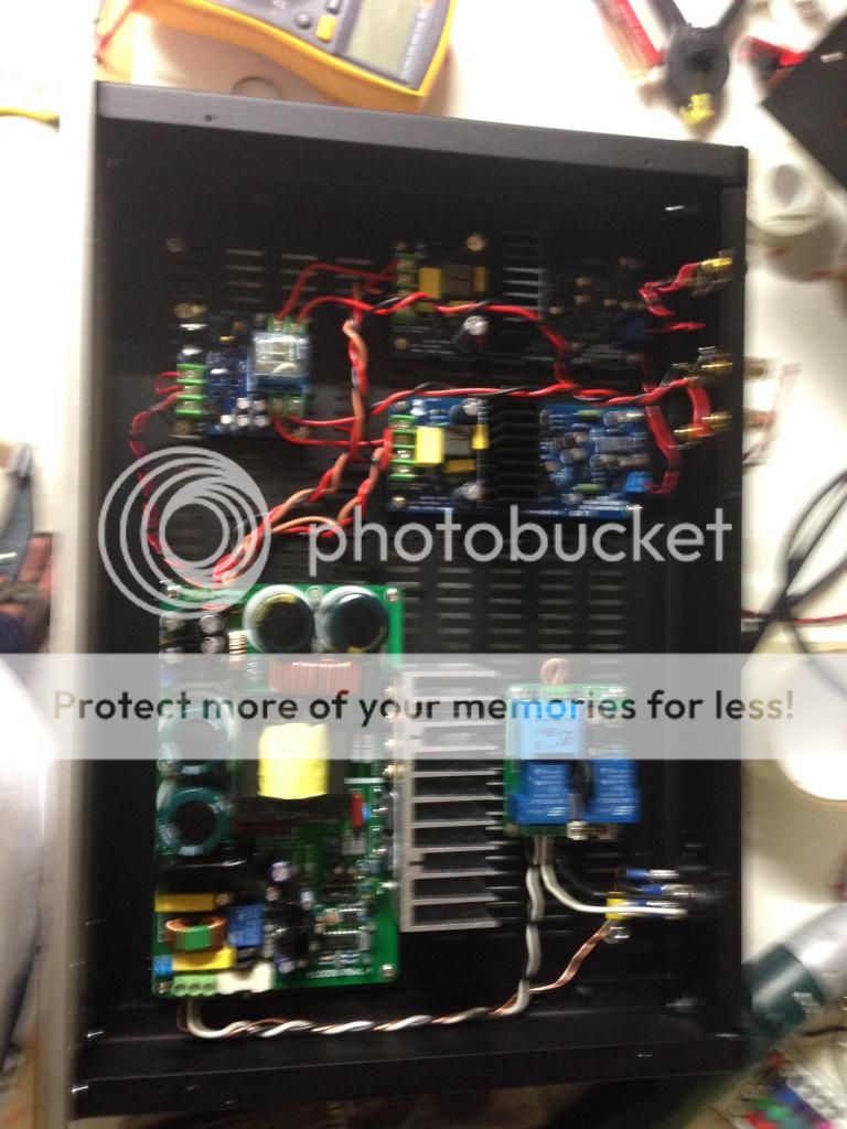
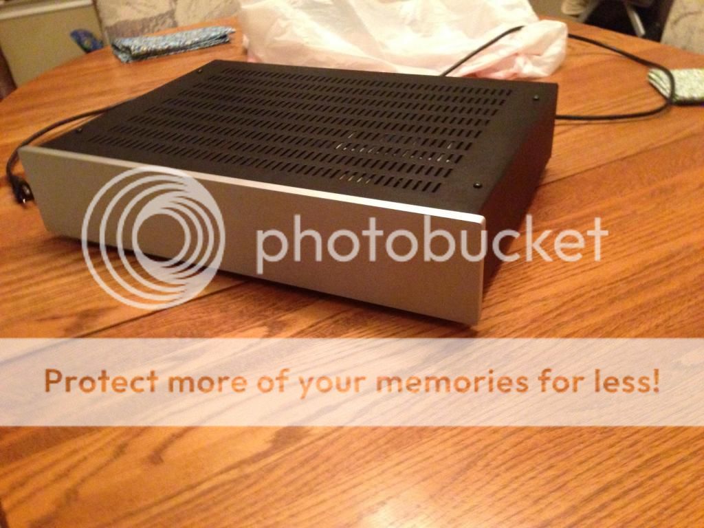
I thought that i should share my Almost finished L25D project 🙂 Still havent added the Speaker protection board, cause i dont have anything to power it with ATM.
Here are som pictures! 🙂
View attachment 282205
View attachment 282206
View attachment 282207
View attachment 282208
View attachment 282209
Do you have the wiring pinout of the software? Christi didn't have it shown on his site.
Ok, got this module all wired up. I have 2. One seems to work, the other appears to be semi dead on arrival.
Here is a video of the malfunctioning module. The LED is dim and is flickering rapidly and it does not work when amplifying. How do I diagnose this?
https://www.youtube.com/watch?v=ue0VYb1C1sM&list=UUMve3R66Q3n72aA3XNpiHEg
I have 60v+- coming from the A1000SMPS and the other module works great. I moved all the wires around and validated the input voltage to the model. I tried upping the voltage out of the SMPS to 62.5v+- still nothing.
Any thoughts?
Unfortunately I bought it over a year ago and just got around to hooking it up. That's probably not an option but I will ask along. Any other thoughts?Returned to the manufacturer.
Unfortunately I bought it over a year ago and just got around to hooking it up. That's probably not an option but I will ask along. Any other thoughts?
Found a solder joint on the bottom of the board that didn't seem to have the metal layer from the PCB attached. Manually created a solder bridge between there and the chip on the bottom. Works now. LED now went out. I'm just getting a new module.
I am impressed with the sound from these little boards. I'll compare it to my ICE Amps tomorrow.
I replaced smoked orig. D class amp from MS909W.
An externally hosted image should be here but it was not working when we last tested it.
An externally hosted image should be here but it was not working when we last tested it.
An externally hosted image should be here but it was not working when we last tested it.
Hi,
I've got a question regarding bus pumping.
I planned to buy L15D for subwoofer use (Dayton Reference 12"), but as bus pumping is a problem with low frequencies and low impedance I'm not sure it is good idea.
Someone here had a solution to drive one channel out of phase, but what to do if I only have one subwoofer?
Thanks.
I just built my first DIY AMP and played with it on my crappy garage speakers last night. It sounds good so this AM I hooked it up to my RTi12's in the living room.
Oddly, when I get my Rotel RSP-1068 to the 73-78db area the speaker protection circuit cuts in and turns the speakers off. The RSP-1068 goes to 95db and doesn't cutout with my RB-1091's (500 watt 8ohm, 1000 watt 4ohm ICE amps) at any level with these speakers.
I've read that these speakers are likely closer to a 4ohm load but why would the speaker protection circuit come on? This is an LJM designed speaker protection circuit.


For bridge mode:Hi,
I've got a question regarding bus pumping.
I planned to buy L15D for subwoofer use (Dayton Reference 12"), but as bus pumping is a problem with low frequencies and low impedance I'm not sure it is good idea.
Someone here had a solution to drive one channel out of phase, but what to do if I only have one subwoofer?
Thanks.
You invert the signal into the second amplifier and use the +ve out on both amplifiers to go to each side of the speaker.
I just assembled a pair of L25D boards from ebay kits. I am using an connex SMPS 800RE set at 60 V +/- and that is exactly what I get at each rail.
With no inputs the amps are quiet. With the inputs shorted they are dead silent. When I plug in an input cable I get terrible buzzing and hissing. The sound comes through faintly but the buzz and hiss are terribly loud.
I am at a loss for what the problem is. I have all inputs and speaker outputs wired as designed.
I plugged it into my preamp (aikido tube) and the SMPS went into protect mode and the blue LEDs cut out.
Just plugged into my phone directly the LEDs stay on but I get the terrible buzz/hiss.
Wondering if 60V is too low?
I had an amp module that was messed up that did the same thing. New module, no issue. The modules themselves are not quiet but will not be audible when listening. Check each module out at a time. I'm running mine on 60v+- from an SMPS 1000 and it's fine.I just assembled a pair of L25D boards from ebay kits. I am using an connex SMPS 800RE set at 60 V +/- and that is exactly what I get at each rail.
With no inputs the amps are quiet. With the inputs shorted they are dead silent. When I plug in an input cable I get terrible buzzing and hissing. The sound comes through faintly but the buzz and hiss are terribly loud.
I am at a loss for what the problem is. I have all inputs and speaker outputs wired as designed.
I plugged it into my preamp (aikido tube) and the SMPS went into protect mode and the blue LEDs cut out.
Just plugged into my phone directly the LEDs stay on but I get the terrible buzz/hiss.
Wondering if 60V is too low?
This noise happens some time when two or more mono classD amplifiers are powered by the same SMPS. It happens also on other amplifiers, not only ljm's.
It has to do with intermodulation between the PWM frequencies of each amplifier.
It is not a defect. Individually, they work fine. Together, intermodulation takes place via common 0V and creates the audible noise.
Usually, the components tolerance make the PWM freq different enough to avoid intermodulation. With some bad luck, noise happens.
Simple solution : one smps per amplifier !
Another option is to replace one board. Statistically, it should work (cf mstang comment).
One can also replace the resistor setting the PWM freq with silgthly different value on one board.
Also, make sure to reference the SMPS 0V to Earth. In some cases, this is enough to remove the noise. It will also remove mains 50Hz/60Hz hum if any.
Last edited:
I just assembled a pair of L25D boards from ebay kits. I am using an connex SMPS 800RE set at 60 V +/- and that is exactly what I get at each rail.
With no inputs the amps are quiet. With the inputs shorted they are dead silent. When I plug in an input cable I get terrible buzzing and hissing. The sound comes through faintly but the buzz and hiss are terribly loud.
I am at a loss for what the problem is. I have all inputs and speaker outputs wired as designed.
I plugged it into my preamp (aikido tube) and the SMPS went into protect mode and the blue LEDs cut out.
Just plugged into my phone directly the LEDs stay on but I get the terrible buzz/hiss.
Wondering if 60V is too low?
Looks like a ground loop or wiring interference to me .
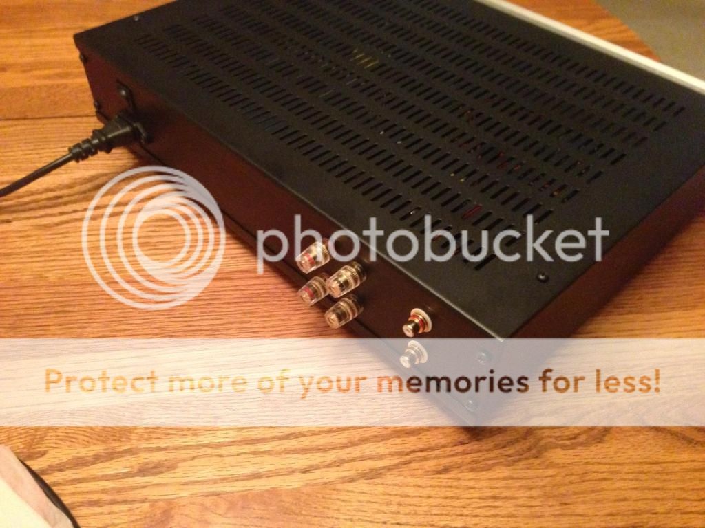
Could you post detailed wiring picture of your amp ?
Cheers ,
Rens
Last edited:
Thanks for the replies! When I got home from work today I swapped the freq resistor on one channel to 470 and that channel cleared up nicely. I ended up putting a 470 in the other channel and the boards play nicely together now. I had son bad ground loop noise with the setup in the pic and I ended up fabing up a star ground with a terminal block and it got a lot better but still not totally quiet. It is worth pushing on and putting it in a chassis.

IR in their designs say carrier frequencies in stereo amps should be as close as possible or off by quite a bit to stop interference.
On my stereo design I added trimmers to the frequency setting circuit so they could easily be changed.
On my stereo design I added trimmers to the frequency setting circuit so they could easily be changed.
Thanks for the replies! When I got home from work today I swapped the freq resistor on one channel to 470 and that channel cleared up nicely. I ended up putting a 470 in the other channel and the boards play nicely together now. I had son bad ground loop noise with the setup in the pic and I ended up fabing up a star ground with a terminal block and it got a lot better but still not totally quiet. It is worth pushing on and putting it in a chassis.
Twist your input wires . Very important ! and use high quality interconnects with class D .
Cheers ,
Rens
- Home
- Amplifiers
- Class D
- My design L20D IRS2092+IRFI4020H 200W8R