I've just done some measurements on my gainstage, and it turns out it is high on H2 as well😉
So I'm driving a 6AS7 which is high on H2 with a gain stage almost as high on H2...No wonder I get high on music...
I'm about to tear my amp apart now and redo the gain stage. Hopefully I will get some better results. Just too bad time is not so available. Once I start ripping this apart, itll be weeks before it's back up and running.
On a good note that means the 6AS7 running SE is a little more linear than I've been thinking.
Member
Joined 2009
Paid Member
On a good note that means the 6AS7 running SE is a little more linear than I've been thinking.
That's good news. I've been looking at the layout of my chasis and trying to design it so that it readily accommodates a choice between 6AS7 and a pair of 6V6s (as an example) potentially makes it a dogs breakfast. I'm thinking that I should backtrack to the idea of making this thing around the 6AS7 and save the experimentation for my 2nd project. If you are finding favourable performance from the 6AS7 this makes my decision a bit easier because I want to end up with a first tube amp that I can be pleased with for some time.
Member
Joined 2009
Paid Member
I find also that without converting to a capacitor loaded psu, which I'm reluctant to do, my B+will limit what I can extract from some of the trioded pentode options.
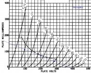
The best option for improved linearity over the 6AS7 remains the very linear looking 6A3 (using 2A3 datasheet) - if these curves can be believed.
With B+ at 230V and using self-bias the plate voltages are just too low for the pentodes.
What I think would be achieved is roughly:
6AS7 2W output at 4.8% distortion
KT66 1W output at 4.9% distortion
6V6GT 3/4W output at 3.2% distortion
6A3 2W output at 1.5% distortion
Member
Joined 2009
Paid Member
You may use tubes you friend gave you then go forward and do something different to compare!
One relatively easy option would be to try another dual power triode that fits in the same socket as the 6AS7.
Look what arrived in the mail today 🙂
Attachments

Member
Joined 2009
Paid Member
I'm not convinced that this tube is any more linear than the 6AS7 but the higher mu certainly makes life easier and it may even be possible to extract more power out of this or use the 5k tap as an option.
In this case I wouldn't use the input transformers.
In this case I wouldn't use the input transformers.
Attachments
Member
Joined 2009
Paid Member
and here's another reason why I'm not going to be simulating this design.. Cathode-follower power amplifiers
Member
Joined 2009
Paid Member
OK, now I have a question for the 'experts' ...
For trying out a pair of 6A3's how do I configure the filament supply - as I have only one 6.3V tap on my power transformer to feed both tubes ??
For trying out a pair of 6A3's how do I configure the filament supply - as I have only one 6.3V tap on my power transformer to feed both tubes ??
Hello,
I'm now playing with donuts as OT.
Have funs
Cheers!
SSView attachment 6080tr1_push_pull.pdf
View attachment 6080tr1ppfft.pdf

I'm now playing with donuts as OT.
Have funs
Cheers!
SSView attachment 6080tr1_push_pull.pdf
View attachment 6080tr1ppfft.pdf
Member
Joined 2009
Paid Member
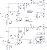
Why only fixed bias is possible ? How about common cathode dc supply (schematic attached - click to expand to full size to make it readable)
Nobody get away with AC heater for this tube without hum problems ??
Santa - Donuts for your latest project ? - I guess you have to be careful to balance the dc accurately as toroids are very unforgiving, is this the purpose of that bipolar transistor ?
Attachments
Hi,
Thanks for your advise.
I found this interesting View attachment 178002
View attachment 178003
View attachment 178004 where're those H2 h3 h4...before clips.
I wonder what would it sounds like.May be this will be my next project.
Cheers!
SS
Thanks for your advise.
I found this interesting View attachment 178002
View attachment 178003
View attachment 178004 where're those H2 h3 h4...before clips.
I wonder what would it sounds like.May be this will be my next project.
Cheers!
SS
Member
Joined 2009
Paid Member
Member
Joined 2009
Paid Member
Well, the big chasis was too big for acceptable WAF so I cut it in half. That gives me two boxes 12" x 8"
I wanted to mount the OTs on their sides, cutting a square hold for the windings to hand through. I cut the holes. There's a metal strip around the outside of the trafo to allow it be mounted standing up so I removed it. The Trafo's fit the chasis nicely. But I discovered that the metal strip around the outside is what holds the trafo together. The trafo falls into two pieces without it. I guess I just learned how they build these things and where the flux gap is !!
So the metal strip has been put back around the trafo's and the chasis scrapped. I'll have to use the 2nd half instead.
Well, the big chasis was too big for acceptable WAF so I cut it in half. That gives me two boxes 12" x 8"
That's easy to say but how did you do it? I have some chassis that also need a resize but, to be frank, a Frankenstein chassis it's not an option for me anymore.
Member
Joined 2009
Paid Member
how? - just pull the cord on the chainsaw and let it rip !
Actually it was simply a case of taking a jig saw to it. You end up with an open side that you fit a piece of polished hardwood to as a frontpiece.
When it goes well it's fun, but otherwise chasis work is a real pain.
Actually it was simply a case of taking a jig saw to it. You end up with an open side that you fit a piece of polished hardwood to as a frontpiece.
When it goes well it's fun, but otherwise chasis work is a real pain.
When it goes well it's fun
I once tried to do what you did with a power jigsaw. Fun it wasn't, chassis started vibrating, couldn't keep a straight line, ruined the black paint finish...
I think I could do it right with a hand saw but it takes too much time. Anyway, good idea to make the chassis smaller. Two tubes for a stereo amp= cute amp.
Member
Joined 2009
Paid Member
I've now managed to cut 3 tube socket holes. Boy what a hassle. Take hand drill and drill 7 or so holes in a circle. Use tin snips to cut between the holes. Pop out the middle. File the sharp bits down. Insert borrowed Greenlee punch and cut proper hole. Need to use mole grips to turn the punch because the bolt head is huge, no spanners to fit. A lot of grunt work. And the only punch sizes I have is 28.3mm (too small) and 30.5mm (too large). I used the large one, the tube sockets don't seem to want to fall through. I can't put a larger drill bit in my drill because it's a 3/8" chuck and all the stepped drill bits I can borrow are 1/2". It's not accurate enough, my 3 tube sockets are not quite in a straight line.
And this is just the experimental chasis to find out if it works, I'll have to build another chasis for the final one.
Solid state was never this much work before you even get to play with the electrons........
And this is just the experimental chasis to find out if it works, I'll have to build another chasis for the final one.
Solid state was never this much work before you even get to play with the electrons........
- Status
- Not open for further replies.
- Home
- Amplifiers
- Tubes / Valves
- my CELLINI triode amp