You can put the Hammond 835 at the very input, then it won't see DC. HF rolloff depends on what impedance you drive them with, if your source is low-Z, it could be all right.
My suggestion: just build the amp as-is and tweak later if needed!
And yes, I agree, h2 is dominant especially in a single-ended amp, but h3+ are also much more audible in small quantities. Still the formula is very nice since it can be graphically determined.
Kenneth
My suggestion: just build the amp as-is and tweak later if needed!
And yes, I agree, h2 is dominant especially in a single-ended amp, but h3+ are also much more audible in small quantities. Still the formula is very nice since it can be graphically determined.
Kenneth
Member
Joined 2009
Paid Member
My plan is to get building it shortly (have to tidy up some wiring and mechanicals on my recent project first) as I have the bits now.
But I like to explore the design options to minimize the need for difficult changes later - most of the effort for me is the construction rather than the design and I figure hacking up the chasis to make space for tube sockets is one of the things I'd prefer to do once. I also like to learn more and going through the design choices teaches me things even if I don't implement them.
I'd say that there are only two key design choices that have to be settled in my mind:
1/ How much voltage gain do I need at the input ?
Is it 20, 30, 40 or 50 ?
2/ How should I achieve that gain ?
Is it a dual triode like 6N1P in a 9pin socket, or 6SN7 in an 8pin socket with input transformer, or single triode like 6C4P requiring two 9pin sockets
I have been considering the option of including a 4pin socket for a 6A3 output tube.
At this point, it all comes down to your source. The 6sn7 with anode choke will give you almost mu (but not quite, because the choke has some DC resistance too). Let's say it gives 20. IIRC you've calculated earlier what voltage you need on the input to get maximum drive. So the question is, can your source deliver it?1/ How much voltage gain do I need at the input ?
Is it 20, 30, 40 or 50 ?
2/ How should I achieve that gain ?
I'd just go with the 6sn7 for starters. When I was younger I made the mistake of sticking in the design phase too long, then I lost interest, and for a long time I actually didn't get anything built... Don't fall into that trap 🙂
I have been considering the option of including a 4pin socket for a 6A3 output tube.
Would be cool but then I'd recommend fixed bias, since you'll be a little on the low side B+ wise. It's easy to add fixed bias later, cannibalize a 12V tranny from an alarm clock radio and add a voltage doubler.
Have fun building!
Kenneth
Member
Joined 2009
Paid Member
I'm afraid I have lots of questions...
Thanks for the advice (unfortunately, I'm no longer young, but I can still learn....)
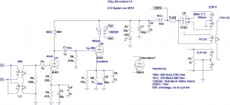
So let's go back to the 6SN7. I like the idea of sticking with Octal bases (that's all I have !). I also like the idea of using up those 835's and configuring them to give me a 1:2 step up along with a bit of ground loop isolation from the source.
Would I wire them as shown in the attached schematic - i.e. with primaries in parallel and secondaries in series ?
The resistor R2 is recommended to terminate the transformer, but I've no clue what value to use here ?
I've added a potentiometer, P1, in parallel with the Cathode resistor to give me the opportunity to tweak the bias. Any concerns ?
The idea of the 6A3 does appeal, although to use the Octal bases I'd plump for the 6B4G. Is fixed bias the best option ? Would this tube operate happily at lower plate voltage or is this a waste ? Could I add some capacitance after the rectifier and boost B+ instead ? Would fixed bias be a good idea for the 6AS7 to save on a 10W cathode resistor ?
I'd just go with the 6sn7 for starters. When I was younger I made the mistake of sticking in the design phase too long, then I lost interest, and for a long time I actually didn't get anything built... Don't fall into that trap 🙂
Thanks for the advice (unfortunately, I'm no longer young, but I can still learn....)
So let's go back to the 6SN7. I like the idea of sticking with Octal bases (that's all I have !). I also like the idea of using up those 835's and configuring them to give me a 1:2 step up along with a bit of ground loop isolation from the source.
Would I wire them as shown in the attached schematic - i.e. with primaries in parallel and secondaries in series ?
The resistor R2 is recommended to terminate the transformer, but I've no clue what value to use here ?
I've added a potentiometer, P1, in parallel with the Cathode resistor to give me the opportunity to tweak the bias. Any concerns ?
The idea of the 6A3 does appeal, although to use the Octal bases I'd plump for the 6B4G. Is fixed bias the best option ? Would this tube operate happily at lower plate voltage or is this a waste ? Could I add some capacitance after the rectifier and boost B+ instead ? Would fixed bias be a good idea for the 6AS7 to save on a 10W cathode resistor ?
Attachments
Fixed bias is a good idea for amps that work in class other than class A. For class A it is better to use a DC feedback so the tube will bias itself as it wants.
Bigun, I am impressed by your learning speed!
What did you do in you previous life? Science most probably?
Bigun, I am impressed by your learning speed!
What did you do in you previous life? Science most probably?
Thanks for the advice (unfortunately, I'm no longer young, but I can still learn....)
Heheh, wasn't implying you were 🙂
Would I wire them as shown in the attached schematic - i.e. with primaries in parallel and secondaries in series ?
The resistor R2 is recommended to terminate the transformer, but I've no clue what value to use here ?
Looks good to me. The resistor at position R2 can be exploited to critically damp the input transformer's resonance (which is created by its leakage inductance and its distributed capacitance) if you know the resonance frequency. This will typically lead to a lower value than 100k but you must keep in mind that the input impedance will be R2 / 4 and your source must be able to drive that. If you don't know the transformer's specifics, 100k or 47k will be fine.
I've added a potentiometer, P1, in parallel with the Cathode resistor to give me the opportunity to tweak the bias. Any concerns ?
It'll scratch when you turn it (pots don't like DC on the wiper), other than that it should be fine.
The idea of the 6A3 does appeal, although to use the Octal bases I'd plump for the 6B4G. Is fixed bias the best option ? Would this tube operate happily at lower plate voltage or is this a waste ?
I generally agree with Wavebourn here but I suggested fixed bias merely to save on B+ voltage. The tube will work at lower voltage but with less power and probably more distortion (just do the 2h thingy to check that). Also you should check if the OPT will work okay with the 6a3, since it has much higher rp than the 6as7.
You could build conversion sockets from octal to 4-pin yourself. The trouble is making them nice enough to look at.
Could I add some capacitance after the rectifier and boost B+ instead ? Would fixed bias be a good idea for the 6AS7 to save on a 10W cathode resistor ?
Yes and maybe: with fixed bias you'll have more power and a different sound -- less SE-like, but tighter bass. I'd say, it's definitely something to try as a hack later on. You may or may not like the result.
Edit: oh and regarding P2: you should either use the center tap, or use the pot to create the ground reference for the heaters. Don't do both at the same time (P2 will have no effect in your case).
Kenneth
Last edited:
Try to stick to the 6AS7 in this one, the 125ESE OPT is rather BW limited and the low rp of said tube will drive it better than a 6B4G or similar. I use the cheapest EDCORs in my kitchen amp and the 6AS7 goes below 20Hz without any problems (though higher harmonics due to core saturation).
Gain: Well, you need about +-70volts peak to drive the 6AS7, so (as Kenneth mentioned) it depends on signals coming in. What is the gain of the 6H8C in your circuit? A 6SN7 will give you a little under 20x gain, which means 2Vrms into the amp will be just fine.
Bias schemes:
In my amps I use a combination. In the RCA datasheet for 6AS7 it is recommended to have a small cathode resistance which provides 7.5volts of cathode bias. (If memory srves me that was the value). I have 100ohm resistors providing me about that voltage, and then a negative voltage for the grid.
In the kitchen amp I only have 135volts on the plates, and I think the grids are at -60volts or so. I get about 3Wrms out of that amp. That's about what you can expect out of your amp. Dont let that stop you, those watts are sweet😉
In my livingroom amp, I have 190 volts on the plates, and the grids are at -85volts. This amp uses One-Electron UBT-1 OPT and even though I use the 16ohm tap into 8 ohms, I can only swing so much current thru it, and end up with a mere 6watts rms. The 6AS7 really needs a lower impedance OPT for max power. Still, the 6watts are wonderful, and when my buds are over for movies, they can't believe the slam and volume the amp gives us.
Anyhow, the bias has been stable and to me gives a good compromise between available voltage swing, distortion, and power.
You will have a bit hum unless you do a bit 'aikido' b/c 100UF just isn't enough with this low rp tube. I use 1000UF in the kitchen amp, and it is ok. My livingroom amp runs twice as hot, and even with 3000UF I still have a little hum. I was actually comfy the way it was, but this forum has poisoned me, and need to get it better. I am now including a CCS type Vregulator and it is promising. For the 'aikido' trick, read about it on tubecad, it works.
However, for this build, I recommend going KISS and just get it done as you've drawn it. Enjoy this amp as you sit up late and design your next one, having learned a lot and not been boggled down by too many things to try and never get anything finished.
Btw. I would reduce R5 to <200kohms. Omit P2 and attach one heater end to the cathode of the output tube. The positive bias of the heater will eliminate any hum from that source.
Member
Joined 2009
Paid Member
What did you do in you previous life? Science most probably?
Thanks for the kind words, and yes, science lurks in my history.
The resistor at position R2 can be exploited to critically damp the input transformer's resonance if you know the resonance frequency.
I've had no luck finding that information, would the answer be to test it - i.e. look for evidence of bad behaviour by feeding the trafo with the 1kHz test signal off my scope and looking at the output from the secondary ?
...Also you should check if the OPT will work okay with the 6a3, since it has much higher rp than the 6as7.
Good question - I checked, rp for the 6B4G is only 800R, which is close to the 6AS7. They are both so much lower than the impedance of the OT primary that I don't see their differences in rp having any affect. But with direct heating I might anticipate a hum problem.
I use the cheapest EDCORs in my kitchen amp and the 6AS7 goes below 20Hz without any problems (though higher harmonics due to core saturation)..
On my recently posted schematic I have downsized the cathode bypass cap for this reason. I figured that 60uF would produce some fall off by 20Hz whereas a larger cap would potentially allow more distortion from the OT. I guess the risk is that residual low freq. AC flowing through the cathode resistor will modulate the bias and cause some IM distortion with the signal ?
Gain: What is the gain of the 6H8C in your circuit? A 6SN7 will give you a little under 20x gain, which means 2Vrms into the amp will be just fine.
Thanks for adding to my confidence on that matter. I keep reading good things about the sound quality of these old 6SN7s. The 6H8C is the Russian equivalent and I have two NOS metal base versions from the 60's; so the mu = 20
Bias schemes:
In my amps I use a combination.....In my livingroom amp, I have 190 volts on the plates, and the grids are at -85volts.
Well, as you say, fixed bias isn't something to consider trying out until it's built, which likely means it'll never happen because I'll be listening to it instead! I may even find that I have a bit more plate voltage with the 270FX because I'm not loading it to it's rated current ?
Omit P2 and attach one heater end to the cathode of the output tube. The positive bias of the heater will eliminate any hum from that source.
I had wondered about the heater bias, I've read that it's advantageous to bias it positively with respect to the cathode. I thought I could do this by hanging a potential divider off B+ and hooking that up to the heater C.T., aiming for 10V above the cathode of the output tube - but strapping it to the Cathode is simpler and that appeals to me.
I will have to order a few parts, I think the chasis I have is too large (17" x 12") for WAF and I need some power resistors anyhow.
I played around with the bias this evening, since I have the hood up to get the Vreg working.
As told by others this tube is not the most linear, I admit it, but the non linearity produces mostly 2nd harmonics.
The 2nd stays pretty constant at a little less than -30dB from a few hundred mV and all the way till approaching clip. The third shows up and is about -65dB at 1watt, gradually increasing till clip, but always below the 2nd and 4th.
There is almost no higher harmonics untill approaching clip.
One weird thing occured at 75mA idle; the 3rd dropped out of sight, only to show up again as I went up/down a few mA from 75mA. I guess this is the optimum operating point with this circuit at the given supply voltage.
So I concur, these tubes are best in a PP config. That said, I really love the sound. Perhaps b/c of the high 2nd harmonic giving a slight touch of warmth? To me this amp is fast and detailed and has great bass. There is no lacking or smearing of any music I try. Then again, according to my wife I'm half deaf, so I might be better off having a low profile regarding sonics😉
Member
Joined 2009
Paid Member
That's interesting and it bodes well for what I hope to achieve. Interesting that there's a sweet spot for low H3, I wonder if this can be predicted from the plate curves ?
Strangely, I'm not looking for low H2 and your favourable opinion of your current amp supports this. It's the famous 'SE Triode' topology that I want to hear. My SS amps are all PP.
Out of interest, have you had a chance to compare the sound of the 6AS7 against a 2A3?
Strangely, I'm not looking for low H2 and your favourable opinion of your current amp supports this. It's the famous 'SE Triode' topology that I want to hear. My SS amps are all PP.
Out of interest, have you had a chance to compare the sound of the 6AS7 against a 2A3?
Member
Joined 2009
Paid Member
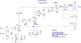
OK so the design is 'final', next step is to order any missing parts.
I've removed the un-bypassed cathode resistor from the input tube (to maximize gain), added a grid stopper to the output tube (mostly out of a habit from SS days), lowered the input trafo termination resistor, lowered the grid-shunt resistor on the output tube, connected the C.T. of the heater winding to the cathode of the output tube and doubled up on the psu input choke (my friend says he has a couple more somewhere) because the current rating of these things is 65mA and I expect to draw 80mA per channel.
I've removed the un-bypassed cathode resistor from the input tube (to maximize gain), added a grid stopper to the output tube (mostly out of a habit from SS days), lowered the input trafo termination resistor, lowered the grid-shunt resistor on the output tube, connected the C.T. of the heater winding to the cathode of the output tube and doubled up on the psu input choke (my friend says he has a couple more somewhere) because the current rating of these things is 65mA and I expect to draw 80mA per channel.
Attachments
Hi,
this should make a very nice amp.
because of the large variations between 6as7 samples you'll need to search the sweet spot for each tube --indeed, of each section-- by hand -- it's pretty much impossible to predict.
I used the Russian 6n8s before and I like it a lot. Very well-built and conservatively specced (this is probably because of the particular economic model in the ussr back then). However, in some of mine the cement between glass and base would come loose very easily.
You asked how to measure the transformer's f_res... I think the easiest is to feed it a square wave and look at the ringing with a 'scope on the secondary. You could even hook up a rheostat and adjust visually for critical damping (aim for quick decay of the oscillation while avoiding bending the flank of the square wave).
Kenneth
Hi,run a simulation.
I've been waiting to see what's gonna in sim..
I've run. See what you'll get.View attachment 6as7gcellse1.pdf
View attachment 6as7gcellse11.pdf
Out of interest, have you had a chance to compare the sound of the 6AS7 against a 2A3?
Negative!
As much as I like the 6AS7 the 2A3 must be as close to perfection as possible. But between the kids, the house, the dog, even the wife, and all other things, more than 10years have past with only the 6AS7 as my companion thru late nights and good wine😉
Seriously though, my 'dream' system is a 2A3 SE amp driving the mids/highs and a 6AS7 PP driving the bass...and I'm not waiting another 10years before that is realized🙂
But for the price, I really do like the 6AS7. It's main hitch being low mu, but made up for the way it handles even 'poor' OPT.
singh santa, thanks!
SemperFi, I'd be interested to hear what you think of the 6n13s, in case you've tried it. It's the russian substitute for 6as7. I have some laying around, planned to use them in stabilized PSUs, but it'd be good to know how they fare with audio.
Kenneth
SemperFi, I'd be interested to hear what you think of the 6n13s, in case you've tried it. It's the russian substitute for 6as7. I have some laying around, planned to use them in stabilized PSUs, but it'd be good to know how they fare with audio.
Kenneth
singh santa, thanks!
SemperFi, I'd be interested to hear what you think of the 6n13s, in case you've tried it. It's the russian substitute for 6as7. I have some laying around, planned to use them in stabilized PSUs, but it'd be good to know how they fare with audio.
Kenneth
I bought a box of 100 of these tubes, all came in the red white and blue (Sovteks) box, and some have the 'winged C' logo as well as the Sovtek logo, some do not...I also have a couple marked in Russian '6n13' that came in the same Sovtek box but bought seperately elsewhere. So I assume they are all made in the same factory, and the brand marking goes a little here and there depending on who's at that post that day, and that person's particular mood etc.
So my guess is that your tube is good to go. Either way I have found every tube so far to be rugged and perform well. (I use most of them in OTL guitar amps).
Member
Joined 2009
Paid Member
Hi,
I've been waiting to see what's gonna in sim..
I've run. See what you'll get.
Whilst tube models for spice seem to be available on the web I'm not so sure about the trafo's - I suspect the idealized models in spice are inadequate, especially for the OT ?
Anyhow, this time around I think I'm going to stick with the old fashioned pen & paper approach.
Member
Joined 2009
Paid Member
Negative!
As much as I like the 6AS7 the 2A3 must be as close to perfection as possible. But between the kids, the house, the dog, even the wife, and all other things, more than 10years have past with only the 6AS7 as my companion thru late nights and good wine😉
Seriously though, my 'dream' system is a 2A3 SE amp driving the mids/highs and a 6AS7 PP driving the bass...and I'm not waiting another 10years before that is realized🙂
But for the price, I really do like the 6AS7. It's main hitch being low mu, but made up for the way it handles even 'poor' OPT.
I suspect I'm not alone when I consider that my time is limited and that I'd like to think I'm going to all the effort to craft a nice amplifier based on using good parts and a good design. Then we find ourselves looking over our shoulders because the 2A3 has this cult following and the 6AS7 does not.
The reputation of the 2A3 gets repeated over time, perhaps growing out of proportion until we reach a point where everyone has to have the same tube - prices go up, diversity goes down.
Still, it would be interesting to hear opinions on the relative merits of the sound of the 6AS7 vs 6A3 (I don't care so much about the differences in mu so long as the circuit delivers enough sound) - are differences large or small.
- Status
- Not open for further replies.
- Home
- Amplifiers
- Tubes / Valves
- my CELLINI triode amp