HI Goran and Danico
Decision made - my Arcam Alpha 5 in the ' crap ' system is going to get the treatment : Nonos, DEM, wood case and fixed transport with top loading.
I'll need your help with some things ( most things !!! ).
It also means I can develop the A5 and leave my favourite Alpha alone for a while - no risks to take with my best machine.
Danico - you convinced me - I can do AB tests and decide which is best for me once I have done the mods based on the excellent information you sent.
Thanks again 🙂
I've done some work on it today and have changed some caps on the dac board - a lot more tomorrow
I'll just e mail this stuff - it'll be boring for the experts and it'll mean i've hijacked the thread😀
Andrew
HI Goran and Danico
Decision made - my Arcam Alpha 5 in the ' crap ' system is going to get the treatment : Nonos, DEM, wood case and fixed transport with top loading.
I'll need your help with some things ( most things !!! ).
It also means I can develop the A5 and leave my favourite Alpha alone for a while - no risks to take with my best machine.
Danico - you convinced me - I can do AB tests and decide which is best for me once I have done the mods based on the excellent information you sent.
Thanks again 🙂
I've done some work on it today and have changed some caps on the dac board - a lot more tomorrow
I'll just e mail this stuff - it'll be boring for the experts and it'll mean i've hijacked the thread😀
Andrew
I knew You will do this! 🙂 And im glad.
Please, post everything here on the thread, it wont be hijacked, oposite, it will became more interesting.
Hey Andrew, I'm glad you made this decision.
It will be interesting to see the progress you make.
We will be here to get you going on.
It will be interesting to see the progress you make.
We will be here to get you going on.
Danico Hi
The attachment - this is DEM re clock ?
Can I try this with all my other chips clocked at the same time ? ( 7310, 7220 and TDA all clocked already ? )
What I mean is : MY CD Player has the standard crystal removed. MY new clock sends 11.2 mhz signal to 7310, 7220 and pin 4 of TDA. My clock then sends another 5.6 mhz clock signal to pin 4 of TDA ( I think that's right ! )
So, leaving all this in place I can then follow the drawing and connect pin 1 to 16/17 using a resistor, zener and cap ?
That's it for DEM ?
Confused 😕
Andrew
Attachments
Danico Hi
The attachment - this is DEM re clock ?
Can I try this with all my other chips clocked at the same time ? ( 7310, 7220 and TDA all clocked already ? )
What I mean is : MY CD Player has the standard crystal removed. MY new clock sends 11.2 mhz signal to 7310, 7220 and pin 4 of TDA. My clock then sends another 5.6 mhz clock signal to pin 4 of TDA ( I think that's right ! )
So, leaving all this in place I can then follow the drawing and connect pin 1 to 16/17 using a resistor, zener and cap ?
That's it for DEM ?
Confused 😕
Andrew
Hey Andrew,
I never tried this kind of DEM clocking. There are many ways doing DEM clock,but the easiest to get from BCK line with 1N5711(or BAT43) 12K resistor to pin16 (pin17 not connected).
And 2k2 from pin16 to -15V.
It should work with 5,6Mhz, I use 2,8Mhz in NOS mod.
The resistor value can be 12 to 15k. for me 15k worked.
If you have inverted clock signal then you can use pin17 with it.
There is a treat on this:http://www.diyaudio.com/forums/digital-line-level/11949-tda1541-dem-reclocking-21.html
Attachments

Last edited:

Danico
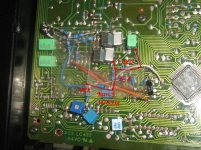
To clock pin 2 and 4 I had to lift the BCK resistor ( nearest leg the chip ) to feed in my new clock signals.
New attachment - your pic - looks like you connected 2K2 and 15 K
to pin 17 ?
Am I wrong ?
Andrew
It really looks like connected to pin17,but I did the pic when I changed the 13K to 15K and it was unsoldered.
pin16 is the way to go.
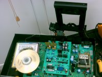
OK, project has started and looks quite funny right now.
Had to short the tray switch wires to make it see the disc and play.
Now, how do I get rid of the loading tray completely Goran ? ( standing up at the back with the motor still in it )
It won't play when I unplug it - do I short that too ?
Andrew
Had to short the tray switch wires to make it see the disc and play.
Now, how do I get rid of the loading tray completely Goran ? ( standing up at the back with the motor still in it )
It won't play when I unplug it - do I short that too ?
Andrew
Attachments
OK, project has started and looks quite funny right now.
Had to short the tray switch wires to make it see the disc and play.
Now, how do I get rid of the loading tray completely Goran ? ( standing up at the back with the motor still in it )
It won't play when I unplug it - do I short that too ?
Andrew
Yes get read of that motor for the mechanism.
There is a micro switch, (at least in my cd 40) when the cd is inside, the mechanism is pushing the switch. You have to look where the switch is located in your player. Press it with your finger just for a second or two, the cd should start spinning to read the data. Of course you can mount a switch to the main panel to make things easier.
Done - works = result !!😀
I'll make a much bigger case to make room for extra transformers, power supplies
and new clock.
I'll also organise a heavy solid support for the laser unit today and see what happens.
Still confused by DEM re clocking but the NOS mod is an easy job.
Just wish I understood it all a bit more😱
I've got the bug now and I'll learn something hopefully
Andrew
Good you make it work, show us how your solid support for the laser look when you'll have it.
Abt DEM reclocking and NOS im sure Danico knows more abt, i have never tried those mods. When ill finish the "ultimate PSU" on my player ill have more time to try NOS, A class, reclocking....
Abt DEM reclocking and NOS im sure Danico knows more abt, i have never tried those mods. When ill finish the "ultimate PSU" on my player ill have more time to try NOS, A class, reclocking....
Thanks, im glad You have them already, its strange, cos i sent the boards to Andrew few days before yours, and he still dont have them.
Goran Hi
Danico is just up the road from you !! 😉
It has further to travel to get here so it's NO problem.
Have plenty to do already !
Andrew
Danico is just up the road from you !! 😉
It has further to travel to get here so it's NO problem.
Have plenty to do already !
Andrew
are you kidding ? 🙂
I remember adding single regulators to the chips and being pretty astonished.
Your boards will take it to a whole different level.
Won't be long for me now - pics soon of my frankenstein monster😀
Just as you reported .. taking all the plastic loading tray bits off completely and just using the laser unit makes an immediately noticeable improvement - and It's still not mounted properly yet 😱
I was not expecting this at all !!
I have so far heard big gains from adding decent power supplies and doing the clocking to various chips simultaneously.
For me this transport / laser unit mod is in the same order of magnitude.
Thanks for this idea.
Andrew
Hi Andrew,
I would suggest you to build separated metal box for the transformer units. This will help in two ways, first, it will result with better sound, cos trafo's wont be near chips, and the second thing, you will have a more space for further mods.
The idea for the "free" laser unit is not mine of course, many people did this before with good results.
I wonder why you still dont have the boards I've sent??? I have a friend in London and it works really much faster when im sending packages there.
Andrew, dont worry, if you need more boards you will have them. First i would like to test them on my player to see if they works ok. Honestly, the price for makeing one board, with costs for posting is less then 5 Euro, so its not worth to charge you 😉 I dont have an intention to make extra money designing boards in first place because this PSU design is not mine idea. When ill finish my own PSU circuit i could think abt earning some extra money (which I need a lot !!! 🙂)
The problem is I dont have much free time to work on it.
Anyway im really glad you started your project and i think it will make this thread much more interesting. Go step by step, dont do all mods at once, believe me its a WRONG way. Every single mod deserve many hours of carefull listening, also many hours for burning-in process. You could generate and record a cd whit "white noise" signal to burn-in your player after every mod.
regards
Goran
Last edited:
Hey Danico and Andrew 🙂
My project is finished unfortunately in a bad way. When i connected the +5V to RAM the smoke was a result 🙂. Cant localize the problem, but player doesnt work anymore. The cd is just spinning all the time. Now im back to my pioneer PD6500 🙁
regards
Goran
My project is finished unfortunately in a bad way. When i connected the +5V to RAM the smoke was a result 🙂. Cant localize the problem, but player doesnt work anymore. The cd is just spinning all the time. Now im back to my pioneer PD6500 🙁
regards
Goran
Oh no - not you too !!?
I've just removed the +5v to ram and 7310 to try and find out what the strange popping / clicking noise is :-(
Also - disc just spinning sometimes then the error message.
Going backwards to find out what I've done.
Taking all the ps off did not cure it.
So now - I have dedicated power only to 7220, all caps changed, laser unit separate and all caps round the dac are 330 nf and 1 uf msb.
These mods are the only ones I can think of that may upset the machine.
I'm completely confused and may leave this project for a while - no patience
left - thanks god I did not do this to my other Alpha.
Can you fix your machine by also going backwards through the mods ?
Andrew
- Status
- Not open for further replies.
- Home
- Source & Line
- Digital Source
- mutting transistors on the output of Marantz cd40 help!!!