Sorry, but you are firmly captured in a Hafler religion.
As long as this takes, no further discussions seems possible.
Succes,
Hans
Hafler himself says that he wants to measure harmonic distortion with his test and that this is being obscured by phase shift and therefor he likes to use a wideband amplifier so that he can measure the harmonic distortion better. So Petr's beliefs are not a Hafler religion, it is his own personal religion that even goes against his admired Mr. Hafler himself!
Bedtime here, maybe I can dream of catching vector errors ;-)
Jan
Jan, see the post:
Musings on amp design... a thread split.
You use the first, or at least the second, testing method, which are at the lowest level of correlation with sound and work only with signals in a steady state. In the steady state, there is no longer any difference what kind of delay the amplifier introduces: 50 ns or 1.5 μs. And for the sound it matters a lot.
This is why progressive developers like John Curl and others use these tests only to verify that products meet specifications. And nothing more. The rest is listened to with ears.
In 1956, this method did not yet exist. I am sure that if he had been known then, the author of the book would have brought him to the highest level.
syn08
«Myself, I have to admit I am having a subjective issue with woofer cones flapping»
Smartly designed amplifiers are DC amplifiers and do not generate loud noises when powered on.
Last edited:
syn08 «Myself, I have to admit I am having a subjective issue with woofer cones flapping»
Smartly designed amplifiers are DC amplifiers and do not generate loud noises when powered on.
You missed the point completely, please read his post in context. He was referring to the need for rumble filters in phono preamps to avoid 'flapping woofers'. This flapping is caused by tone arm resonances at the very low freq range.
BTW I have a tip for you: this thread here give a very good overview of the issues involved in using sound cards for very sensitive measurements:
DIY soundcard intended for measuring amplifiers
About progressive designers: do you call designers that haven't produced any new circuits for the last 40 years 'progressive'? That interesting.
Jan
Last edited:
Maybe petr can explain us, how is possible in real use to hear in the same time music signal at the input of amp and at the output of amp (delayed by fractions of uS ) and to create and perceive audio "vector error" by ears??.
Or he claims that man is able to hear pure delay about 1uS and bandlimit to some 300kHz?? 🙂
Or he claims that man is able to hear pure delay about 1uS and bandlimit to some 300kHz?? 🙂
Isn't that a wonderfull result ?You guys seem to be in violent agreement.
We can't have it all, can we 😀 😀Poor me, I will never find out WTF are "vector errors", or at least the right English language translation.
Hans
Finally got to the place where I have my copy of Jiri Dostals'book on opamps. I thought I had the original edition but memory teased me, I have the EDN re-issue.
On page 156 he starts the discussion on Vector, Amplitude and Phase errors.
In reverse order:
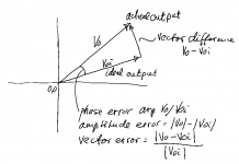
1 - the phase error is the phase shift between input and output. This error can be presented as a difference in angle between the input magnitude vector and the output magnitude vector, with both vectors starting at the origin;
2 - the amplitude error is the difference between the length (magnitude) of the two vectors described in (1) above;
3 - the vector difference is the length of a vector connecting the endpoints of the two vectors mentioned in (1).
The vector error then is the absolute value of the amplitude error divided by the absolute value of the ideal output vector.
In Dostals' view, the vector error is the decisive measure of the accuracy of the operational circuit, the deviation from an ideal circuit, and that seems sensible.
The rough circuit attached shows the definitions used by Dostal.
Don't forget that this book is about opamps, operational circuits and their deviations from an ideal circuit. In that context vector error could be a useful metric.
I have no clear idea what it would mean in the audio context, whether it would be useful there. Comments invited.
Jan
On page 156 he starts the discussion on Vector, Amplitude and Phase errors.
In reverse order:
1 - the phase error is the phase shift between input and output. This error can be presented as a difference in angle between the input magnitude vector and the output magnitude vector, with both vectors starting at the origin;
2 - the amplitude error is the difference between the length (magnitude) of the two vectors described in (1) above;
3 - the vector difference is the length of a vector connecting the endpoints of the two vectors mentioned in (1).
The vector error then is the absolute value of the amplitude error divided by the absolute value of the ideal output vector.
In Dostals' view, the vector error is the decisive measure of the accuracy of the operational circuit, the deviation from an ideal circuit, and that seems sensible.
The rough circuit attached shows the definitions used by Dostal.
Don't forget that this book is about opamps, operational circuits and their deviations from an ideal circuit. In that context vector error could be a useful metric.
I have no clear idea what it would mean in the audio context, whether it would be useful there. Comments invited.
Jan
Attachments
Last edited:
Yes, it's like a loudspeaker crossover, you want the signals to add up at the output in vector form, amplitude and phase, not just amplitude. It took a few decades for loudspeaker manufacturers to understand that lol.
Ironically, vector error only makes sense when signals can be represented by complex numbers or phase/amplitude vectors, which means single frequency steady state, and definitely not first cycle.

Here's a 12kHz gated sine (middle plot, blue). Its spectrum (top, blue) is all over the place, it contains all frequencies both above and below 12kHz. This signal cannot be represented as vector. Removing low frequencies in the spectrum with a linear phase brickwall filter (top plot, orange) gives a signal with a different shape (middle plot, orange). Bottom plot is the difference.
If the sine signal is not gated, but instead static:

Then the brickwall filter does not change it at all, because its 12kHz frequency is above the 6k brickwall cutoff. Therefore the output is identical to the input, and the error is just floating point rounding errors around 10^-15.
This filter has no vector error, the 12kHz signal goes straight through without phase shift or attenuation. But by removing frequencies below 6kHz, it does change the shape of the gated sine, which petr would call "first cycle distortion" (why not) ; that process has nothing to do with vector error obviously.
Ironically, vector error only makes sense when signals can be represented by complex numbers or phase/amplitude vectors, which means single frequency steady state, and definitely not first cycle.
Here's a 12kHz gated sine (middle plot, blue). Its spectrum (top, blue) is all over the place, it contains all frequencies both above and below 12kHz. This signal cannot be represented as vector. Removing low frequencies in the spectrum with a linear phase brickwall filter (top plot, orange) gives a signal with a different shape (middle plot, orange). Bottom plot is the difference.
If the sine signal is not gated, but instead static:
Then the brickwall filter does not change it at all, because its 12kHz frequency is above the 6k brickwall cutoff. Therefore the output is identical to the input, and the error is just floating point rounding errors around 10^-15.
This filter has no vector error, the 12kHz signal goes straight through without phase shift or attenuation. But by removing frequencies below 6kHz, it does change the shape of the gated sine, which petr would call "first cycle distortion" (why not) ; that process has nothing to do with vector error obviously.
The point is that something calling an error right away, immediately triggers the feeling that something is wrong, because we don’t want errors.
When calling deviations just differences to start with, could start an investigation whether this is erroneous, or just harmless to what extend and in what application this can be seen as acceptable or not.
For measuring equipment you need completely different parameters as for audio, for medical equipment or for avionics to name a few.
Hans
In linear system, the deviation of the amplitude and the phase shift go hand in hand.
Just keep a flat frequency response across audio band. That implies you won't get much phase shift within audio band.
Also human is not that sensitive to either amplitude "error" or the phase "error". 10% Amplitude "error" is less than 1dB in loudness. Your room EQ has much greater amplitude "error" than this.
However, human is sensitive to THD. I don't have golden ears, but I still can hear -60dB THD (0.1%). Just play a pure sin wave tone, and you can hear the difference, too.
The point is that something calling an error right away, immediately triggers the feeling that something is wrong, because we don’t want errors.
When calling deviations just differences to start with, could start an investigation whether this is erroneous, or just harmless to what extend and in what application this can be seen as acceptable or not.
For measuring equipment you need completely different parameters as for audio, for medical equipment or for avionics to name a few.
Hans
Yes Hans, the input signal between opamp input pins is often called an input error signal, because with an infinite gain ideal opamp that signal should be zero. So the tendency is to call it an error because it deviates from zero.
But from the point of view of signal processing it is the actual opamp input signal! It cannot be zero because then there would be no output signal. In a practical opamp, the input signal is Vout/Aol, definitely not zero, and definitely not an 'error'.
One mans error is another man's input 😎
Jan
The Hafler test appeared after all the known methods (five main methods) of testing, listed by Rakovsky in his 1956 book, were investigated.
Unfortunately, until today this method has not found widespread use, with the exception of the author himself and Bob Carver.
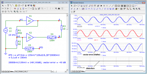
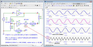
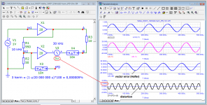
Let's consider the work of the Hafler test using ideal components as an example.
Unfortunately, until today this method has not found widespread use, with the exception of the author himself and Bob Carver.
Let's consider the work of the Hafler test using ideal components as an example.
Attachments

Do you notice a difference between your posts and from others over the last few days?
I will tell you: those other posts explain what the graphs show, the set up, why things are done a certain way, and help to understand the shown data.
Your posts basically throw up a bunch of graphs and hope that we somehow figure out what your point is.
You could be 10 times as effective in 1/10th of the time if you tried to communicate.
Jan
Last edited:
You could be 10 times as effective in 1/10th of the time if you tried to communicate.
That's a non sequitur, since you are assuming efficiency and/or time matters for him.
On this side of the pond, we call his tactic "throw jello against a wall and see if it sticks", although "****" would be a much more appropriate material.
Last edited:
The Hafler test appeared after all the known methods (five main methods) of testing, listed by Rakovsky in his 1956 book, were investigated.
Unfortunately, until today this method has not found widespread use, with the exception of the author himself and Bob Carver.
Of course not. It was the best they had at the time, but very soon much better methods were invented, and today anybody with a $115 soundcard and free software can measure 10 or 100 times as sensitive as the Hafler test.
One would have to be pretty stupid to go back to an old test method that is much less sensitive when you have the right tools for a better test almost freely available.
Or long back to the good (?) old times 😎
Jan
Last edited:
I think it would be possible to use a variant of the Hafler test, in order to get a partial null of the fundamental (or both fundamentals if it's an IMD test). This would reduce the amplitude of the signal to be acquired by the ADC, thus minimizing the distortions added by the ADC and its frontend circuits.
I was thinking about this for IMD: use two soundcard channels to output 19k and 20k so they don't intermodulate in the DAC and soundcard output circuits. If the DUT amplifier is inverting, its input is a virtual ground, so both signals can be summed while the soundcard output opamps of each channel only provide current for their own 19k or 20k, but not both. So that should create an IMD-free input signal.
Now, use another inverting opamp to sum the amp's output signal and the two input signals. This would remove a large part of 19k and 20k, making the job easier for the ADC.
Even a low quality null of 20dB would significantly reduce the soundcard contribution to IMD, and it should be possible to get that without fiddly adjustments.
- Home
- Amplifiers
- Solid State
- Musings on amp design... a thread split