Hans, your example also shows that the smaller the group delay, the less distortion the signal is subjected to. Any deviation from the original is a distortion, no matter how we call it. The smaller the group delay and the more constant it is in a larger frequency range, the shorter the transients and the less distortion associated with them.
So putting a low pass filter in is distortion? More stupidity! You may as well call gain a distortion too.
Petr, I give up.
You make riduculous correlations between everything that stills your hunger to prove something.
I’m with DBD. Well said.
Hans
You make riduculous correlations between everything that stills your hunger to prove something.
I’m with DBD. Well said.
Hans
Last edited:
“Gold-ear” listeners claim that the appearance of a constant component during the operation of the servo control system of more than 30 ... 40 mV is already noticeable in the sound.
However, let's not deviate from the topic: "the influence of the time Propagation Delay on the accuracy of amplification of audio signals"
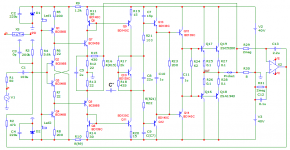
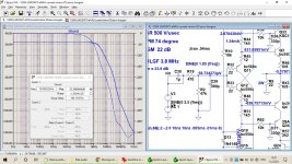
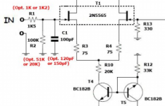
Baxandall made a great contribution on this topic. Among Russian radio amateurs, I. Akulinichev continued his work. He also used a vector meter to measure distortion. Here is one of his developments with a slight modification to increase the output power.
The quiescent current of the output transistors (bias) is 125 mA, the signal propagation delay time is not more than 50 ns and is stable up to a frequency of 4 MHz. Due to this, at a frequency of 200 kHz, there is no gain roll-off, the output signal practically merges with the input signal multiplied by Ku. The distortion spectrum is short, falling, the 2nd harmonic prevails in the spectrum. Class AB amplifier, but no switching distortion. The servo control signal level at 20 Hz is less than 90 dB (norm is less than 40 dB) than the input signal level.
The rest of the parameters are reflected in the test results and are presented in the figures.
The delay can not only be associated with the frequency ,
but also with the signal level, although this is not always easy to see.
if the delay is related to frequency, this is the worst case. In this case, the amplitude envelopes of the signals will be violated, and the associated sound timbre
I have already given the circuit of the serial production of the Kumir U-001 amplifier, which still sounds decent today.
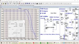
Engineers who understand what parameters are required from the amplifier develop them like this, see the attached file.
The slew rate of the output voltage depends on the С*-correction and can be from 150 to 1800 V / μs. The time to reach the steady state does not exceed 30 ns, unlike other amplifiers in which the time of transient processes (distortions) is delayed to 3 or more microseconds.
Attachments
... and now phase shift is called 'vector error'. I had a good morning laugh ;-)
Jan
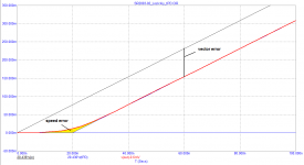
Jan, sit down, "two"! you still do not understand the difference between vector error and phase shift.
The phase shift at a given frequency depends on the delay time (the time axis is horizontal). And the vector error is voltage! (vertical axis). Learn the theory.
Petr
It must be a very special feeling to know that you are the only one in the world making sense, everybody else being stupid!
I wish I had that feeling, but I'm too stupid for that 😎
Jan
I wish I had that feeling, but I'm too stupid for that 😎
Jan
😉
It's a sin to laugh at an old man.
I am older than he is, so I am allowed 😉
Jan
Jan, do you agree with the statement of Cyril Hammer?
If the amplifier had enough bandwidth of 30 kHz with an output voltage slew rate of 5 V / μs, then today amplifiers with a bandwidth of 5 MHz and higher would not be designed.
Personally, I agree with Cyril Hammer and with my tests I try to show that he is right, that's all.
If the amplifier had enough bandwidth of 30 kHz with an output voltage slew rate of 5 V / μs, then today amplifiers with a bandwidth of 5 MHz and higher would not be designed.
Personally, I agree with Cyril Hammer and with my tests I try to show that he is right, that's all.
I am confused with the terms used by some of Russian participants and by explanations, specially those used by petr-.
Use of delay is very confusing, like Group delay, Propagation delay and some others “delay”
OOS used instead NFB, correction instead compensation, I really can’t follow all that discussions, even if I would like to learn something from it.
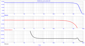
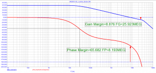
Attached a gain plot of one of my amps, without and with input LF filter, and from those plots it’s easy to see that input filter has biggest influence on Group Delay.
The bump in the gain plot is characteristic of the TPC compensation (not correction as petr- uses instead).
Damir
Use of delay is very confusing, like Group delay, Propagation delay and some others “delay”
OOS used instead NFB, correction instead compensation, I really can’t follow all that discussions, even if I would like to learn something from it.
Attached a gain plot of one of my amps, without and with input LF filter, and from those plots it’s easy to see that input filter has biggest influence on Group Delay.
The bump in the gain plot is characteristic of the TPC compensation (not correction as petr- uses instead).
Damir
Attachments
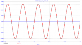
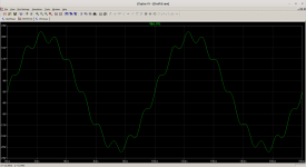
In the following image we can see a 1KHz signal modulated by a 100Hz signal,
if an amplifier has different delays depending on the signal level,
the 1KHz signal will have phase errors.
Our ear will perceive that with jitter.
I think it is the biggest problem affecting audio amplification.
if an amplifier has different delays depending on the signal level,
the 1KHz signal will have phase errors.
Our ear will perceive that with jitter.
I think it is the biggest problem affecting audio amplification.
Attachments
The simplest way to measure vector distortion on any signal was suggested by Hafler. There is no need for any measuring instruments, everything is heard with the ears. If you wish, you can look at it with an oscilloscope, or even a voltmeter. But with a voltmeter, you will see only the average value (like the temperature of patients in the hospital, taking into account those in the morgue). I am receiving letters of thanks that I raised this topic. People achieve the lowest possible level of vector distortion and the sound is significantly improved. So you shouldn't laugh. We say: "laughs the one who laughs last"
Jan, do you agree with the statement of Cyril Hammer?
If the amplifier had enough bandwidth of 30 kHz with an output voltage slew rate of 5 V / μs, then today amplifiers with a bandwidth of 5 MHz and higher would not be designed.
First of all, I have no idea what Cyril Hammer's statement is.
Secondly, you clearly do not understand audio marketing.
Think about this analogy: why are there 100's if not 1000's of different cars that all do the same thing: bring you from A to B.
Jan
Can you show an example of this instead of FCD?if the delay is related to frequency, this is the worst case. In this case, the amplitude envelopes of the signals will be violated, and the associated sound timbre
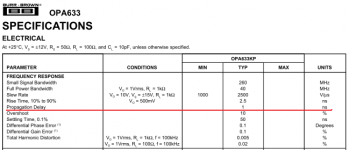
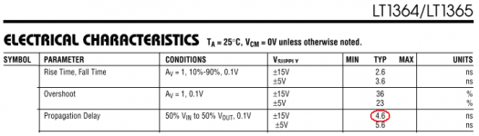
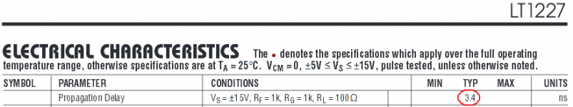
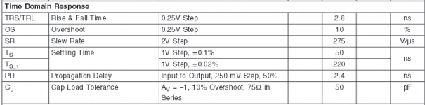
Damir, the time Propagation Delay is sometimes indicated in the datasheets on the op-amp
Nobody has installed a low-pass filter at the input with a cutoff frequency of 160 kHz for a long time.
Here are some examples.
Or they don't put any filter at all, in extreme cases put a filter with a cutoff frequency of 1 MHz or higher.
Otherwise, it would not make sense to design amplifiers with a full power bandwidth of 5 MHz or higher.
Moreover, many companies refuse servo control and a capacitor in the NFB circuit to ground. Input capacitors are used with a capacity of at least 220 μF (instead of 0.47 μF) - two capacitors connected in anti-parallel.
Attachments
-
 OPA633_tPD.png35 KB · Views: 279
 -
 LT1364_LT1365_tPD.png27.4 KB · Views: 282
 -
 LT1227_tPD.png14.7 KB · Views: 115
 -
 LMH6601_tPD.png21.2 KB · Views: 116
 -
 HK6800-HK6900.png23.7 KB · Views: 143
 -
 Goldmund_M3.png38.9 KB · Views: 153
 -
 AVR65_HK6950_PA2400.png21.6 KB · Views: 147
 -
 AV1200_HK6100_HK660_HK680.png19.6 KB · Views: 135
Damir, the time Propagation Delay is sometimes indicated in the datasheets on the op-amp
Nobody has installed a low-pass filter at the input with a cutoff frequency of 160 kHz for a long time.
In my example the cutoff was at 850 kHz not 160 kHz.
Propagation delay is used in digital circuits.
Nobody has installed a low-pass filter at the input with a cutoff frequency of 160 kHz for a long time.
Or they don't put any filter at all, in extreme cases put a filter with a cutoff frequency of 1 MHz or higher.
Otherwise, it would not make sense to design amplifiers with a full power bandwidth of 5 MHz or higher.
Have you ever read Stereophile, and if so have you ever seen an amp with a BW of 5Mhz. I haven't.
Has it ever crossed your mind that no source is producing this kind of frequencies, not digital or analog.
So what's the benefit of not using an input filter, none. What's in favor: yes, suppression of HF.
Moreover, many companies refuse servo control and a capacitor in the NFB circuit to ground.
Input capacitors are used with a capacity of at least 220 μF (instead of 0.47 μF) - two capacitors connected in anti-parallel.
Just another nonsense argument.
I know for instance that most if not all Mark Levinson main amps have a capacitor in the NFB to ground and a 2.2uF polypropylene input cap.
As mentioned before, you are postulating things out of the blue.
You can't put feathers on a dog and call it a chicken.
Hans
- Home
- Amplifiers
- Solid State
- Musings on amp design... a thread split