Who is not interested in what I am writing about - just walk by and do not flood, have pity on your colleagues.
Anyone who wants to understand the intricacies of designing amplifiers and the nuances of their work, I hope, will find a lot of useful information for themselves.
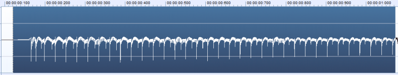
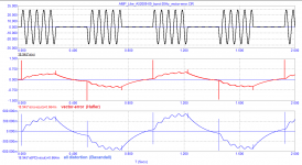
Added one more test signal for the servo control system, see the file in the archive. It can be fed from the output of a sound card or burned to a CD. The servo control system reacts differently to each of the five signals.
Anyone who wants to understand the intricacies of designing amplifiers and the nuances of their work, I hope, will find a lot of useful information for themselves.
Added one more test signal for the servo control system, see the file in the archive. It can be fed from the output of a sound card or burned to a CD. The servo control system reacts differently to each of the five signals.
Attachments
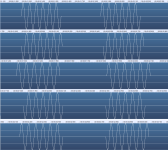
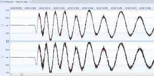
An example of checking the operation of the servo control system
Pay attention to the response of the servo control to the first sinusoid in bursts.
Everyone can check the work of the servo control in their amplifier using the test signals that I posted in the archives.
Pay attention to the response of the servo control to the first sinusoid in bursts.
Everyone can check the work of the servo control in their amplifier using the test signals that I posted in the archives.
Attachments

I make a prediction, like Vanga blindly-the frequency of the cutoff of the servo control node has been reduced. That's all the revision.
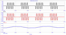
I hope you are aware that the sine bursts are essentially digital amplitude modulation (amplitude shift keying-ASK). You can read an article on Wikipedia called "Амплитудная манипуляция". By the way, it also says that the spectrum at steep edges of the switching signal expands very much (this is about your and Graham's FCD distortions)
About your test signals - do you really think that your sound card will give you this kind of signal? You first try to see with an oscilloscope what you will have at the output. At the same time, show us, I will be happy to make a mistake and agree with you, greatly surprised.
There are very few sinusoidal signals in audio signals, and the onset of a signal that looks like a large-amplitude sinusoid is not uncommon. Moreover, there are fragments with an introduction close to rectangular or triangular signals.
Therefore, you fagos, there is still a lot to be surprised at until you begin to understand something.
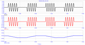
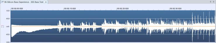
On the audio signals, I showed how, with the servo control system, in some amplifiers, a constant component of up to ± 250 mV or more appears within a fraction of a second. At the same time, if you turn off the servo control system, this does not happen, i.e., parasitic modulation of the formant envelopes does not occur.
Here are some snippets from audio tracks, some of which I may have already shown.
Therefore, you fagos, there is still a lot to be surprised at until you begin to understand something.
On the audio signals, I showed how, with the servo control system, in some amplifiers, a constant component of up to ± 250 mV or more appears within a fraction of a second. At the same time, if you turn off the servo control system, this does not happen, i.e., parasitic modulation of the formant envelopes does not occur.
Here are some snippets from audio tracks, some of which I may have already shown.
Attachments

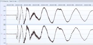
So it's as if you don't see your own horse-like time scale and refuse to understand that in fact these creepy-looking curves are slow signals? And besides, I repeat, what of this will you see ON the OUTPUT of the sound card? Will the source allow you to reproduce this?
I can be surprised by real arguments, not by speculation and myths. Show your synthesized bursts at the output of the sound card in the form that you showed us here in the pictures. That will be the argument.
I can be surprised by real arguments, not by speculation and myths. Show your synthesized bursts at the output of the sound card in the form that you showed us here in the pictures. That will be the argument.
Fagos, I suspect that he has no access to required measurement gears nor does he show any knowledge on how a signal on real measurement looks like. I have not seen him show real measurement, only simmed results.
fagos, for skeptics like you, I have laid out the "arguments" (synthesized signals) in the archive in the form of 1-second wav-files. What prevents you from downloading them and playing them from a sound card. If you need a longer duration, I can increase it. But I think that with a modern storage oscilloscope there is no problem to consider the processes taking place in 1 second.
Play these "arguments" from your sound card and be amazed.
People like you will not believe anyone until they see everything with their own eyes.
I hope nothing prevents you from doing this and showing a photo from the oscilloscope screen so that everyone is convinced of the identity of the results
Play these "arguments" from your sound card and be amazed.
People like you will not believe anyone until they see everything with their own eyes.
I hope nothing prevents you from doing this and showing a photo from the oscilloscope screen so that everyone is convinced of the identity of the results
To petr-2009:
It is a very clever move to shift the burden of proof to the opponent, but these are your theses and you need to prove them. And what is the credibility of my results, if you do not even believe my words, as well as the words of other participants in the discussion. So the burden of proving your theories is on you.
It is a very clever move to shift the burden of proof to the opponent, but these are your theses and you need to prove them. And what is the credibility of my results, if you do not even believe my words, as well as the words of other participants in the discussion. So the burden of proving your theories is on you.
Musings indeed. I Scour this forum for new inspiration.
Some just fight.
Throw some schemas up for me to Assimilate. 😀😀
OS
Some just fight.
Throw some schemas up for me to Assimilate. 😀😀
OS
offtopic:
fagos, teach the theory. But it is not enough to know it, it must be understood. And it will be like a translation of Putin's statement.
Something like this was translated Putin's childish joke addressed to Baydon: “how who calls others, he himself is such” or, more simply, everyone judges others by himself, what he himself is - he thinks that everyone is like that. Thus, Putin made a subtle hint.
And in the translation they turned it over: "a fisherman sees a fisherman from afar." It turned out that Putin agreed
Musings indeed. I Scour this forum for new inspiration.
Some just fight.
Throw some schemas up for me to Assimilate. 😀😀
OS
Back on page 14 in post 138 there is a circuit due to an enthusiast named Akulinichev that had incidental interest for me because of the all NPN output stage.
In the commentary it was claimed Akulinichev followed the work of Baxandall and built a vector meter.
Unfortunately there were no specific references to the work Baxandall or Akulinichev and his meter, and so there were no links, and the fast moving discussions moved to yet another argument.
I happen to have a couple of issues of Wireless World dating to 1978 and in the May issue the third in the series on Audio Design is titled "Nyquist and Bode Diagrams".
In the opening statement as above, Baxandall said that although the Nyquist diagram is seldom actually drawn it is the best starting point one can make to gain and understanding of the preferred techniques in preferred in amplifier design.
He uses the terms of basic voltage phasor diagrams and Nyquist diagram. There is a conclusion on thoughts due to Bode at the end.
The full series of Baxandall's articles is available on member Bonsai's website Audio Power Amplifier Design – Peter J Baxandall
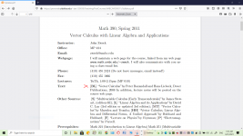
A google search on Peter Baxandall shows he is a co-author of a book entitled "Vector Calculus" which is reference material for at least one study course.
Maybe the articles inspired the book?
Attachments
Last edited:
A google search on Peter Baxandall shows he is a co-author of a book entitled "Vector Calculus" which is reference material for at least one study course.
I'm fairly sure that's a different Peter Baxandall.
Further research shows you are correct - Peter R Baxandall is a mathematician, and Peter J Baxandall was an Audio Engineer who died in 1995 - my mistake.
The first diagram in the May 1978 Wireless World in Peter J's article shows a four terminal representation of a voltage gain block - also a subject among others in 1969 work by Hans Liebeck co-author of Vector Calculus published in 1986. Perhaps that may just be a pure coincidence but it does look odd.
The first diagram in the May 1978 Wireless World in Peter J's article shows a four terminal representation of a voltage gain block - also a subject among others in 1969 work by Hans Liebeck co-author of Vector Calculus published in 1986. Perhaps that may just be a pure coincidence but it does look odd.
Attachments
Back on page 14 in post 138 there is a circuit due to an enthusiast named Akulinichev that had incidental interest for me because of the all NPN output stage.
In the commentary it was claimed Akulinichev followed the work of Baxandall and built a vector meter.
Unfortunately there were no specific references to the work Baxandall or Akulinichev and his meter, and so there were no links, and the fast moving discussions moved to yet another argument.
I happen to have a couple of issues of Wireless World dating to 1978 and in the May issue the third in the series on Audio Design is titled "Nyquist and Bode Diagrams".
In the opening statement as above, Baxandall said that although the Nyquist diagram is seldom actually drawn it is the best starting point one can make to gain and understanding of the preferred techniques in preferred in amplifier design.
He uses the terms of basic voltage phasor diagrams and Nyquist diagram. There is a conclusion on thoughts due to Bode at the end.
The full series of Baxandall's articles is available on member Bonsai's website Audio Power Amplifier Design – Peter J Baxandall
A google search on Peter Baxandall shows he is a co-author of a book entitled "Vector Calculus" which is reference material for at least one study course.
Maybe the articles inspired the book?
'Our' Peter Baxandall died in 1995, many years before 2008, the date of the article.
Jan

'Our' Peter Baxandall died in 1995, many years before 2008, the date of the article.
Jan
I had seen the print copy of Vector Calculus book co-authored by Peter R Baxandall was published in 1986 by Oxford Clarendon Press but omitted this fact for brevity.
The site I accessed shows there are print copies in two libraries miles distant from where I live in this country. This site could be useful in searches for out of print material.
After naming the attachment PRB, for the books author, I thought hmm, in lower case, the probe in Tian plot simulations.
Attachments

- Home
- Amplifiers
- Solid State
- Musings on amp design... a thread split