Jan, I showed the scheme in which the operation of the servo control system and its parameters in various modes of operation was checked repeatedly. Therefore, you have no reason to say that I am testing like Hans a piece of the circuit.
if you find an error, tell me where it is
if you find an error, tell me where it is
Attachments
Yes, there is a very good reason because your Servo is the worst design ever, even wasting an expensive AD844.
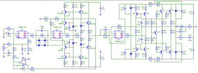
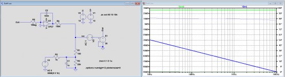
Look ate the circuit diagram below, a first order servo using the same components but without AD844, a circuit that is absolutely stable without any of your circuits anomalies.
The people who used your servo for decades where ignorant of it's extremely bad behaviour and so are you.
Hans
Look ate the circuit diagram below, a first order servo using the same components but without AD844, a circuit that is absolutely stable without any of your circuits anomalies.
The people who used your servo for decades where ignorant of it's extremely bad behaviour and so are you.
Hans
Attachments
Jan, I showed the scheme in which the operation of the servo control system and its parameters in various modes of operation was checked repeatedly. Therefore, you have no reason to say that I am testing like Hans a piece of the circuit.
if you find an error, tell me where it is
I am not saying that! I am trying to suggest to you a possible cause to your LF oscillation so you can fix it. If you are not interested in fixing your circuit, that's your choice. But don't put words in my mouth I didn't say. Let's try to stay honest.
And, while we are speaking about honesty, you should not publish copyrighted material on this public forum. It is clearly spelled out in the rules.
Jan
Last edited:
Jan, if you do not understand how your servo control system works, these are your problems. I'm just trying to open your eyes. I do not appropriate other people's schemes and do not give them out as my own, I always give a link to the source.
Hans, I repeat. This is not my servo!
Hans, I repeat. This is not my servo!
Last edited:
Hahahahaha! I need more popcorn.
You have a design that oscillates at LF and you have no idea, and try to blame it on someone who's circuit you stole. You're unique!
Jan
You have a design that oscillates at LF and you have no idea, and try to blame it on someone who's circuit you stole. You're unique!
Jan
Last edited:
Thanks for asking - right shoulder is A-OK. Tuesday I have a meeting with the surgeon to discuss the various technical options and take a decision and plan a date. Probably again a 3D printed insert.
I'll be as good as new when the pandemic is over 😎
Jan
I'll be as good as new when the pandemic is over 😎
Jan
Petr, and I repeat that you don’t know what you are doing. Change the servo as I have show without the AD844 and you will be surprised to find out that you were pushing air.Hans, I repeat. This is not my servo!
Hans
Hahahahaha! I need more popcorn.
You have a design that oscillates at LF and you have no idea, and try to blame it on someone who's circuit you stole. You're unique!
Jan
here are the wav tracks for testing servo control systems.
Jan, check your system at the control points that I indicated and show the oscillograms, let's laugh together
Attachments
I am not going to check anything. We concluded that your amp oscillated.
If you chose to disregard that and yet again try to go to another subject, another method, whatever, without fixing the underlying problem, I am not going to spend any time here.
Have a nice Sunday,
Jan
If you chose to disregard that and yet again try to go to another subject, another method, whatever, without fixing the underlying problem, I am not going to spend any time here.
Have a nice Sunday,
Jan
here are the wav tracks for testing servo control systems.
Jan, check your system at the control points that I indicated and show the oscillograms, let's laugh together
If you don't listen to anybody and just keep sending pictures without any meaning, why should someone take the trouble of investing any time in proving that you are wrong ?
When you have the guts, send me a .Wav file of your multitone recording an do another test with your adjusted servo without AD844.
I'm afraid this is not going to happen because you don't want to be convinced of the opposite like a true believer.
Hans
To avoid any wrong impressions, I think it is useful to recap what's going on lately.
Some days ago Petr_2009 once again changed the subject and claimed that a servo in his amp increased noise at the LF end. It was pointed out that his FFT was badly specified so he was looking at a high LF FFT floor. He did not fix the FFT, what would be the logical thing to do, to be sure that it was servo noise, but started showing graphs in the time domain.
It was apparent from those that his sim amp was unstable and showed LF oscillations, and this was pointed out to him.
He then claimed it was the fault of the servo designer, a circuit he copied from the internet, and which was part of a totally different design that was specifically designed to illustrate error correction concepts, and therefor had an unusual servo arrangement, a fact Petr did not realize.
Again, as would be logical, he did not fix the LF oscillation but posted .wav files and asked that we listen to them. I don't know what the goal was, what we were supposed to hear, what kind of amp we are listening to compared to the simulated one, and what the input signal was.
At that point I decided I am not going to invest more time in this. I believe that in the course of this thread, enough advice has been given to Petr_2009 on how to make meaningful and understandable posts that could make for useful discussions and knowledge transfer. I have no idea what his goal is with all these posts.
Jan Didden
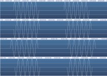
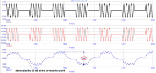
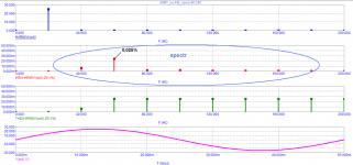
Here is another version of the audio track for testing the servo control system.
The signal is applied to the input of the amplifier and, using an oscilloscope, they look at the signal at the output of the integrator and other control points (depending on the specific circuit) four tracks are different combinations of 20 Hz burst
For each of the tracks, the system will react (or, as Yang says - "excited") in different ways.
Well, then, since Jan took the position of an ostrich, I appeal to all forum visitors: if anyone has such an amplifier or an amplifier with a similar servo control system, please conduct tests and post oscillogram photos so that one channel has an output signal, and the second channel of the oscilloscope has a signal at the output of the interactor, etc.
Jan, files need to be viewed with an oscilloscope and eyes, not ears
Attachments
Didn’t I say it before ?
You are the closest thing on this Audio Forum to an LP with a scratch, with one difference, an LP does not insult people. 😀
Hans
You are the closest thing on this Audio Forum to an LP with a scratch, with one difference, an LP does not insult people. 😀
Hans
Hans, you have a crooked idea about insults and rudeness.
I know two branches where they really insulted and rude to Graham absolutely not understanding what he was talking about. This does not mean at all: "This cannot be - because it cannot be."
Hans, you first figure out who is trying to humiliate or offend whom. I am not laughing at your posts, as some have laughed at Graham's posts and my posts.
In this thread, the same is happening only in relation to me. Point to at least one of my posts where I laugh at someone's words. I understand that you have no arguments, so there is nothing left to do but laugh. Well, continue in the same spirit and further.
I say that is rude.... Well, then, since Jan took the position of an ostrich, ...
Jan and Hans posted serious arguments, but You simply ignored them (or not understood). You have at least to think about and try to understand what are they talking and learn from experienced members.I understand that you have no arguments..
BV, show me at least one even frivolous argument
How we got the arguments in the form of empty chatter about nothing.
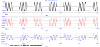
Here are some more arguments about servo control tests.
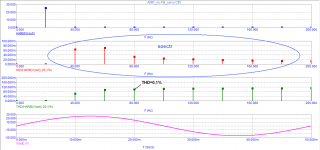
I tested the original circuit and this same circuit after modifying the servo control system. The rest of the scheme remained unchanged.
Conclusions, I hope you will do it yourself
after revision, the distortions decreased by 4 times, especially the spectrum of higher harmonics decreased
How we got the arguments in the form of empty chatter about nothing.
Here are some more arguments about servo control tests.
I tested the original circuit and this same circuit after modifying the servo control system. The rest of the scheme remained unchanged.
Conclusions, I hope you will do it yourself
after revision, the distortions decreased by 4 times, especially the spectrum of higher harmonics decreased
Attachments
- Home
- Amplifiers
- Solid State
- Musings on amp design... a thread split