Petr,
I think you have created a monster.
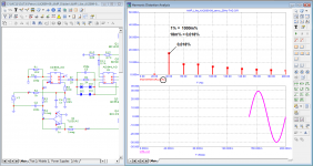
I simulated your circuit, see image below.
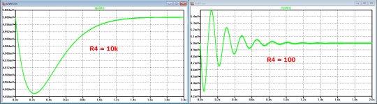
Because of the combination of used resistor values, you effectively divide the Integrator output by 10, giving roughly the the same effect as a RC time 10 times as long.
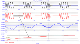
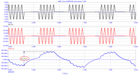
See first image below, where the green line shows the input to your 26dB amp, the red line the input to the AD844 from the integrator and the blue line the signal after being attenuated by 20dB at the output of the AD844.
When removing the 100nF cap behind the integrator, the circuit becomes instable!! and when reducing R4 to have less attenuation, the system starts to motorboat, a typical effect of a servo with a second order filter, here made visible in an obvious way.
So that your DC output level with servo is going up and down is nothing to be surprised of, sorry for that.
Hans
I think you have created a monster.
I simulated your circuit, see image below.
Because of the combination of used resistor values, you effectively divide the Integrator output by 10, giving roughly the the same effect as a RC time 10 times as long.
See first image below, where the green line shows the input to your 26dB amp, the red line the input to the AD844 from the integrator and the blue line the signal after being attenuated by 20dB at the output of the AD844.
When removing the 100nF cap behind the integrator, the circuit becomes instable!! and when reducing R4 to have less attenuation, the system starts to motorboat, a typical effect of a servo with a second order filter, here made visible in an obvious way.
So that your DC output level with servo is going up and down is nothing to be surprised of, sorry for that.
Hans
Attachments

Hans, I took a ready-made, and I hope everyone knows the scheme from the Internet. I did not invent anything or alter the servo control circuit. I did not assemble this amplifier in hardware and did not hear how it sounds.
Jan, the music signal is not periodic. I don’t know how to decompose it into a spectrum using the Microcap I use, but I don’t need it, it’s not interesting to me, because you don’t understand anything in that mess.
For musical signals, the methods of Baxandall and Hafler are more suitable, which I most often use.
In this case, I tried to show the mechanism of signal distortions associated with the operation of the servo control system using simple methods.
I tried to show the mechanism of signal distortions
Try already convolution and step response windowing functions. Run from dementia.
In this case, I tried to show the mechanism of signal distortions associated with the operation of the servo control system using simple methods.
Then why did you introduce the music signal in this test?? If you want to prove the impact of a servo, you must make sure that ALL other conditions are the same with or without the servo. You must make sure that the test signal with and without servo is exactly the same in each case, also that the amp, the supply, etc. is exactly the same.
We unusually call this the 'scientific method'.
Jan
Hans, I took a ready-made, and I hope everyone knows the scheme from the Internet. I did not invent anything or alter the servo control circuit. I did not assemble this amplifier in hardware and did not hear how it sounds.
In this case, I tried to show the mechanism of signal distortions associated with the operation of the servo control system using simple methods.
So you are trying to prove something with an amplifier that you don’t own or even heard.
And although I have explained that an Integrator produces only a signal with opposite polarity while attempting to get rid of DC at the amp’s output, doing that with a signal that is much much lower in level and that it’s contribution can be considered as distortion free, despite all this you persist in calling this a distortion mechanism.
Distortion has to come from somewhere with a reason. Well in this case there is not one single reason to explain.
I had lot’s of patience so far, hoping that you were on the brink of something new, but you don’t want to listen or even go into a real useful discussion.
The nonsense you try to sell relating to Servo's is just as wrong as your noise theory with multitones, as is the importance of a very low GD etc, etc.
You turned out to be an convinced devotee of graphics, to your feelings telling it all without any reserve.
But fighting feelings with facts is a dead ending street, so I give up and wish you good luck.
Hans
Last edited:
So you are trying to prove something with an amplifier that you don’t own or even heard.
And although I have explained that an Integrator produces only a signal with opposite polarity while attempting to get rid of DC at the amp’s output, doing that with a signal that is much much lower in level and that it’s contribution can be considered as distortion free, despite all this you persist in calling this a distortion mechanism.
Distortion has to come from somewhere with a reason. Well in this case there is not one single reason to explain.
I had lot’s of patience so far, hoping that you were on the brink of something new, but you don’t want to listen or even go into a real useful discussion.
The nonsense you try to sell relating to Servo's is just as wrong as your noise theory with multitones, as is the importance of a very low GD etc, etc.
You turned out to be an convinced devotee of graphics, to your feelings telling it all without any reserve.
But fighting feelings with facts is a dead ending street, so I give up and wish you good luck.
Hans
Hi Hans
Good post.
Welcome to the club, I gave up a long time ago.
Stein
if you don't understand what's what, then running from dementia won't help youRun from dementia.
Attachments
I have two comments.
Firstly, remember that when you 'switch on' the amplifier, as you do here, it starts with all capacitors uncharged. Then the servo starts to tune in, and you see that nicely in figure 5. During that run in period, which is longer than 4 cycles at 20Hz, the bias situation in the input circuit is slowly changing. What that does to the distortion, who knows.
Secondly, you show some audio transients and conclude that music is more than sine waves. That is like kicking in an open door, everybody here knows that.
What you must realize is that even these transients, in the audio band, are relatively slow waves. Compared to the infinitely fast signals you like to use, those music transients are more like slowly varying DC!
BTW Why do you still show the harmonics as mV level? It is almost impossible to see small differences that way. That is the reason everybody (except you) uses a dB scale for the distortion.
Jan
Last edited:
Why do you still show the harmonics as mV level?
Jan, the impression is that you see similar charts for the first time. I am embarrassed to have to explain even such things. See attached file
Attachments
I don't see them for the first time, I see them from you all the time. I think they are very bad, almost impossible to get the details.
Also, you do not show the units. Now you say it is %, but it is easy to think it is mV.
As I said, that is why the rest of the world (except you) uses a dB scale.
Jan
Also, you do not show the units. Now you say it is %, but it is easy to think it is mV.
As I said, that is why the rest of the world (except you) uses a dB scale.
Jan
Last edited:
Jan, every time you surprise me more and more
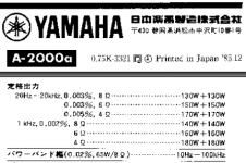
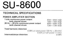
If you find at least one manual for an amplifier with an indication of distortion in dB, then inform Personally, I have not found any
Distortions in% are understandable to any user, any cook
Only in manuals on amplifiers of recent developments can one find duplication of% and dB
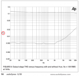
I show the dependence of distortion on frequency with the voltage level at which it was measured as here
If you find at least one manual for an amplifier with an indication of distortion in dB, then inform Personally, I have not found any
Distortions in% are understandable to any user, any cook
Only in manuals on amplifiers of recent developments can one find duplication of% and dB
I show the dependence of distortion on frequency with the voltage level at which it was measured as here
Attachments


If you look at other measurements on this forum, you'll see that dB scale is the most used when displaying a thd spectrum. % is more common for overall specifications or for sweeps vs frequency or power. Furthermore, I've never seen a graph labelled in m%. mV are common though, hence Jan understandable mistake.
This said, you seem to have picked a point of detail to fight about, rather than addressing Jan main points, which are way more important and valid.
This said, you seem to have picked a point of detail to fight about, rather than addressing Jan main points, which are way more important and valid.
I guess the confusion is caused by the use of milli-percents. I have never seen anybody use "m" for this. I have sometimes seen "pcm" to indicate "per cent mille" but not in audio. So if you change the vertical scale to display percents (i.e. change 10.000m to 0.01%) you have less confusion.
Martti
Martti
at the bottom of all graphs it is indicated in which units the measurements were made; for measuring distortions, the scale in % is selected
the scale is set automatically and can only be changed by the Microcap programmer. So questions and suggestions to the developers of the program. Prefixes mile (m or 1/1000), micro (u or 1/100000) and so on are international. It's strange that you don't know how to use them.
Standard measuring instruments such as Audio Precision also measure distortion in%
Last edited:
Let me help you, from the uCAP user manual (bold mine):
You can step input level and/or frequency and create plots of THD, THDN (with noise), SINAD, SNR, and any harmonic vs F, VIN, VOUT, PIN, or POUT. Plots can be done as voltage or power ratios in dB, %, or simple numeric format.
But there is another important consideration. If I want to present proudly my discovery to members, it is my task to make it as simple and easy as possible for the members to understand what I am trying to say.
If members indicate they are confused trying to follow my reasoning or data, I must take action for that, because I am the guy who wants to communicate something to others.
This has been a big issue in this whole thread.
So much good work would be lost if nobody understands wtf I am talking about.
Jan
The output signal throws up and down by 200 ... 250 mV, which in my opinion is unacceptable. Then we wonder why it sounds worse with the servo control system.
the servo control signal (blue) is fed to the input of the amplifier and, as a result, it turns out to be an output with a useful signal
the servo control signal (blue) is fed to the input of the amplifier and, as a result, it turns out to be an output with a useful signal
Attachments
I think Hans has already indicated that this servo system, due to the RC times involved, is unstable. Indeed, unacceptable!
Jan
Jan
Jan, Hans promised to test two amplifiers with a multitone. Until now, I don't see any test results.
Then he started modeling. One of two things: it has a curve simulator or arms. The servo control circuit borrowed from here, its performance has been tested for a decade, so it is at least frivolous to say that it is inoperable,
Then he started modeling. One of two things: it has a curve simulator or arms. The servo control circuit borrowed from here, its performance has been tested for a decade, so it is at least frivolous to say that it is inoperable,
Attachments
Nobody says it is inoperable. You really should be more critical to your own work, instead of spending your time how to trash other people.
Your servo appears to be instable. That should be clear from the graph you posted. You were blind to it because of your pre-occupation to prove that FCD stuff.
This instability can for instance happen if there are several RC times in the servo feedback circuit that interact with the low frequency response of the amp.
If you copy parts of somebody else's work without having an understanding of the complete circuit, things like this can happen.
You often see this with tube amps, and it is called motorboating, because it can sound like a motorboat.
Jan
- Home
- Amplifiers
- Solid State
- Musings on amp design... a thread split