Yeah, 'ours' is Peter J.
AES SILVER MEDAL AWARD
Peter J. Baxandall
The AES recognizes and honors those who have made outstanding contributions to the field of audio in engineering, technology, service, and the arts through its Awards Program.
In 1993, Peter J. Baxandall was presented with the AES Silver Medal Award for his significant contributions in the field of audio electronics.
Peter has a daughter which I have been in contact with when doing the reprint of some of his previously unpublished work with Douglas Self, as at the time he had been passed away for several years.
Jan
Last edited:
Musings indeed. I Scour this forum for new inspiration.
Some just fight.
Throw some schemas up for me to Assimilate. 😀😀
OS
how do you like this version of the amplifier based on the amplifier by Hiraga
Attachments
Back on page 14 in post 138 there is a circuit due to an enthusiast named Akulinichev that had incidental interest for me because of the all NPN output stage.
In the commentary it was claimed Akulinichev followed the work of Baxandall and built a vector meter.
Unfortunately there were no specific references to the work Baxandall or Akulinichev and his meter, and so there were no links, and the fast moving discussions moved to yet another argument.
I happen to have a couple of issues of Wireless World dating to 1978 and in the May issue the third in the series on Audio Design is titled "Nyquist and Bode Diagrams".
In the opening statement as above, Baxandall said that although the Nyquist diagram is seldom actually drawn it is the best starting point one can make to gain and understanding of the preferred techniques in preferred in amplifier design.
He uses the terms of basic voltage phasor diagrams and Nyquist diagram. There is a conclusion on thoughts due to Bode at the end.
The full series of Baxandall's articles is available on member Bonsai's website Audio Power Amplifier Design – Peter J Baxandall
A google search on Peter Baxandall shows he is a co-author of a book entitled "Vector Calculus" which is reference material for at least one study course.
Maybe the articles inspired the book?
Vector calculus is a course every EE and most other engineers take in there first or second year. Its been around at least since Maxwells equations. Nothing to do with "speed error".
Your paper is full of opinions and errors.
"As the NFB depth increased, the THD level decreased, and an adequate increase in sound quality, paradoxically, did not occur." Proof. I mean real proof, not your insesint ramblings.
"As it turned out, it is the attack and decay of the sound that determine the timbre of the sound, the differences between one note in different instruments."
Nonsense. Acording to you a sustained note (the attack is long gone and the decay hasnt happened) has no timbre, so a long violin note sounds like a long piano sustain if I didnt hear the attack. Its the harmonics that give timbre.
How much of the rest of that paper is made up nonsense?
Variants of the vector distortion selector proposed by I. Akulinichev and not only: Radio 1977-06, Radio 1980-04, Radio 1983-10, Radio 1989-10, Radio 1993-01, Radio 1990-06
indra1 (Alex) There is such an anecdote about "smells bad": Oh, and I don't like this Senkevich! Don't like it - don't eat.
Just don't sniff, I already asked those who like to flood - just walk by
cbdb, what you call a mistake is taken from lectures on psychoacoustics by I. Aldoshina
indra1 (Alex) There is such an anecdote about "smells bad": Oh, and I don't like this Senkevich! Don't like it - don't eat.
Just don't sniff, I already asked those who like to flood - just walk by
cbdb, what you call a mistake is taken from lectures on psychoacoustics by I. Aldoshina
Last edited:
Anecdote is your articles. To pull excerpts from various literary sources without taking into account the context, without even leaving specific references in the list of references - this is your method. Being rude in response to a request to provide evidence is also your method. Shift the actual measurements and work to others ... yes, sir.indra1 (Alex) There is such an anecdote about "smells bad": Oh, and I don't like this Senkevich! Don't like it - don't eat.
Just don't sniff, I already asked those who like to flood - just walk by
cbdb, what you call a mistake is taken from lectures on psychoacoustics by I. Aldoshina
Regarding the cbdb comments:
You blindly refer to authoritative sources to cover up your own misunderstanding of the issue. The sound attack is not the first period specifically, but rather the shape of the envelope as the signal increases. See the envelope sections in the attachment (A — attack, D-decline, S-support, R-release).

First of all, you should understand the terminology, and then copy the excerpts. I'm sure Aldoshina knows the terminology better than you do.
I told him that ages ago, I don't know whether it went over his head or not, I don't care anymore. Planet 10 has even referred the rise of a sine wave as an envelope, sometimes one is tempted to give up entirely with gurus.The sound attack is not the first period specifically, but rather the shape of the envelope as the signal increases.
fagos, do not attribute to me what I did not say. I have never and anywhere said that the first period is a signal attack. Only you could have come up with such nonsense. As they say what a person is like - he thinks that everyone is like that.
As for measurements, I use the simplest operation in the program - subtraction. This is what the Baksandall vector distortion selector concludes. Simpler operations for measuring vector errors were proposed by Hafler and Jiri Dostal. These are well-known works to which he has given references many times.
If you, fagos, need proof that 4 - 2 = 2, and not 3 or 5, then you are need in kindergarten. There they will quickly prove it to you on apples or cubes.
You say I'm attributing something to you, but you still haven't recognized the fallacy of the first cycle's misrepresentations, which you voted for with both hands. What does this mean? You keep saying that the Gram was not understood, and the measurements on the stationary signals do not correlate with the sound quality. And you do not take the arguments of the forum participants for careful consideration. Am I getting something wrong? Is FCD no longer relevant?fagos, do not attribute to me what I did not say. I have never and anywhere said that the first period is a signal attack. Only you could have come up with such nonsense. As they say what a person is like - he thinks that everyone is like that.
If you, fagos, need proof that 4 - 2 = 2, and not 3 or 5, then you are need in kindergarten. There they will quickly prove it to you on apples or cubes.
Well, then explain why you are always trying to attach transients to the sound quality assessment. I will ask a simple question: "Can you name the condition for the occurrence of a transient process in the amplifier?"
P.S. I don't need to tell you where I need to be and where I don't need to be. That's something I can do perfectly well without you, don't worry.
Meanwhile every reader may may have noticed your ignorance and mean behaviour in insulting each member who do not share your queer opinions. So what?fagos, do not attribute to me what I did not say. I have never and anywhere said that the first period is a signal attack. Only you could have come up with such nonsense. As they say what a person is like - he thinks that everyone is like that.
As for measurements, I use the simplest operation in the program - subtraction. This is what the Baksandall vector distortion selector concludes. Simpler operations for measuring vector errors were proposed by Hafler and Jiri Dostal. These are well-known works to which he has given references many times.
If you, fagos, need proof that 4 - 2 = 2, and not 3 or 5, then you are need in kindergarten. There they will quickly prove it to you on apples or cubes.
THIS IS UTTERLY BORING!
bucks bunny, it’s strange that you didn’t notice when some colleagues were stocking up on popcorn and laughing at Graham and me.
fagos, I have explained to you dozens of times what the distortions of the first period are. I'll try to make one more try
By distortions of the first period, I looked through 2 branches from beginning to end:
https://www.diyaudio.com/forums/solid-state/32758-cycle-distortion-graham.htm
The many faces of distortion
Graham's opponents argue that there are no first-period distortions. The main argument is: "This cannot be because it cannot be." I did not find any other arguments, mostly empty chatter.
Graham cited arguments from radio technical reference books and other literature and argued that the term "linearity" refers only to the steady state when there is a deviation of phase and amplitude and there are no additional products of distortion.
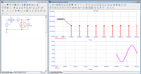
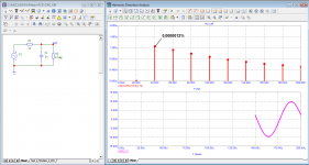
Consider the distortion of the first period on the simplest RC circuit with a cutoff frequency of 80 kHz, made on ideal passive components. By definition, such a circuit cannot introduce harmonic distortion. Amplifiers with this bandwidth are not uncommon. First, let's try to measure the distortion at a frequency of 20 kHz in the 50th period (this is the maximum value that the program allows). It can be seen from the test that even at the 50th period, the transient processes have not yet completely ended, and in addition to the phase shift and a decrease in the signal amplitude, we see a small level of distortion products.
The minimum number of periods for testing is four. Let's check the spectrum for the 4th period. As can be seen from the test for the 4th period, the level of additional components became higher.
In order to deceive the program, we use a small trick and delay the signal by 3 periods so that the 4th period is the first. The program will use it to measure the spectrum of distortions.
It turns out that a simple RC-circuit in the first period, in addition to a phase shift and a decrease in the signal amplitude, introduces additional distortion products of 1.7%.
I am sure that at the 1000th period, or even later, only a phase shift and a decrease in amplitude will remain in the signal, and no additional distortion products. This is what is meant by the term "linearity" which Graham was trying to explain.
I hope it is clear that the less the signal propagation delay and the larger the frequency band it will have a constant value, the less distortion will be in the first period. Only on pure sinusoidal signals, distortions are significantly reduced after several periods (see the test on the 4th period compared to the first). But the musical signal has a complex impulse character, so for it every moment is equivalent to the first period.
fagos, I have explained to you dozens of times what the distortions of the first period are. I'll try to make one more try
By distortions of the first period, I looked through 2 branches from beginning to end:
https://www.diyaudio.com/forums/solid-state/32758-cycle-distortion-graham.htm
The many faces of distortion
Graham's opponents argue that there are no first-period distortions. The main argument is: "This cannot be because it cannot be." I did not find any other arguments, mostly empty chatter.
Graham cited arguments from radio technical reference books and other literature and argued that the term "linearity" refers only to the steady state when there is a deviation of phase and amplitude and there are no additional products of distortion.
Consider the distortion of the first period on the simplest RC circuit with a cutoff frequency of 80 kHz, made on ideal passive components. By definition, such a circuit cannot introduce harmonic distortion. Amplifiers with this bandwidth are not uncommon. First, let's try to measure the distortion at a frequency of 20 kHz in the 50th period (this is the maximum value that the program allows). It can be seen from the test that even at the 50th period, the transient processes have not yet completely ended, and in addition to the phase shift and a decrease in the signal amplitude, we see a small level of distortion products.
The minimum number of periods for testing is four. Let's check the spectrum for the 4th period. As can be seen from the test for the 4th period, the level of additional components became higher.
In order to deceive the program, we use a small trick and delay the signal by 3 periods so that the 4th period is the first. The program will use it to measure the spectrum of distortions.
It turns out that a simple RC-circuit in the first period, in addition to a phase shift and a decrease in the signal amplitude, introduces additional distortion products of 1.7%.
I am sure that at the 1000th period, or even later, only a phase shift and a decrease in amplitude will remain in the signal, and no additional distortion products. This is what is meant by the term "linearity" which Graham was trying to explain.
I hope it is clear that the less the signal propagation delay and the larger the frequency band it will have a constant value, the less distortion will be in the first period. Only on pure sinusoidal signals, distortions are significantly reduced after several periods (see the test on the 4th period compared to the first). But the musical signal has a complex impulse character, so for it every moment is equivalent to the first period.
Attachments


THIS IS UTTERLY BORING!
Is there any other non-audio forums where thing can go on and on like this here? I found none.
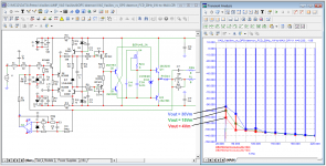
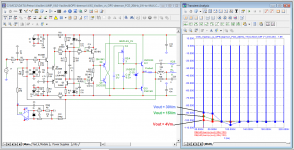
Many people will object to me, they say, what does RC-chain distortion have to do with amplifier distortion?
The most direct. The shorter the signal transmission delay time (for example, Cyrill Hammer believes that the delay time should be only a few ns), the less distortion is noticeable by ear.
In the LF region, distortion reduction is facilitated by the implementation of the amplifier in the form of a DC amplifier.
But DC amplifiers often use a servo control system that can have a negative effect on the signal.
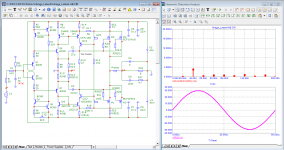
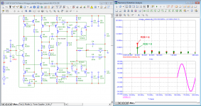
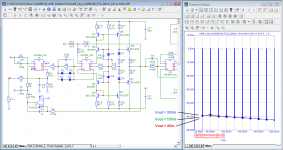
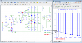
Well, now let's compare two DC amplifiers with servo control systems (they are already familiar to you from the settings above).
Laughing lovers can stock up on popcorn.
The most direct. The shorter the signal transmission delay time (for example, Cyrill Hammer believes that the delay time should be only a few ns), the less distortion is noticeable by ear.
In the LF region, distortion reduction is facilitated by the implementation of the amplifier in the form of a DC amplifier.
But DC amplifiers often use a servo control system that can have a negative effect on the signal.
Well, now let's compare two DC amplifiers with servo control systems (they are already familiar to you from the settings above).
Laughing lovers can stock up on popcorn.
Attachments
OK, but you still haven't answered:fagos, I have explained to you dozens of times what the distortions of the first period are. I'll try to make one more try
Graham cited arguments from radio technical reference books and other literature and argued that the term "linearity" refers only to the steady state when there is a deviation of phase and amplitude and there are no additional products of distortion.
The point is that you should draw the red line that separates the conditionally stationary signal at the input from the conditional non-stationary signal.I will ask a simple question: "Can you name the condition for the occurrence of a transient process in the amplifier?"
And I don't need fairy tales about the pulse nature of the sound signal. I would take my oscilloscope and look at the waveform on the toughest grater I could find in my library. When stretching along the time axis to a half-period of 20 kHz per cell, everything is smooth and it is ridiculous to even think that the amplifier will not be able to work it out. There were overloaded guitars with a fairly rigid spectrum, and cymbals with as high a frequency as possible, and dense rich vocals. And nothing. Do not believe me - you yourself referred to Baxandal and his research of the records, where he also found nothing. Or does he have no faith now, since it doesn't fit with your and Graham's theory?But the musical signal has a complex impulse character, so for it every moment is equivalent to the first period.
Many people will object to me, they say, what does RC-chain distortion have to do with amplifier distortion?
The most direct. The shorter the signal transmission delay time (for example, Cyrill Hammer believes that the delay time should be only a few ns), the less distortion is noticeable by ear.
In the LF region, distortion reduction is facilitated by the implementation of the amplifier in the form of a DC amplifier.
But DC amplifiers often use a servo control system that can have a negative effect on the signal.
Well, now let's compare two DC amplifiers with servo control systems (they are already familiar to you from the settings above).
Laughing lovers can stock up on popcorn.
Peter, the thread is 40 pages long, whatever you are claiming, is it possible to confirm that with real world prototype and measurements or not?
If yes, why haven't you done it already? If no, what is the point of all this?
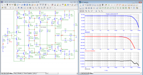
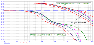
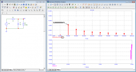
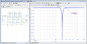
To understand what happens during transient processes, let's look at the example of a notch filter at a frequency of 20 kHz.
More than 500 dB rejection of 20 kHz signal - essentially a near-perfect distortion meter
Signal with a frequency of 30 kHz and above is suppressed by only 6 dB (2 times)
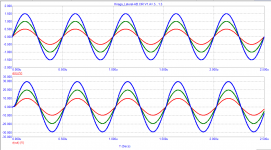
Take a 20 kHz signal at 10 V peak and add the 3rd harmonic at 1 V peak to it and see how long it takes to get distortion products at the filter output.
It turns out that a time of at least 1 ms is required with a period of the main signal of only 50 μs.
Not surprisingly, no distortion meter can measure signal distortion in its first periods.
Roughly speaking, approximately the same processes occur with the signal and in amplifiers during transient processes, but they are not seen by any distortion meter, not a single spectrum analyzer.
More than 500 dB rejection of 20 kHz signal - essentially a near-perfect distortion meter
Signal with a frequency of 30 kHz and above is suppressed by only 6 dB (2 times)
Take a 20 kHz signal at 10 V peak and add the 3rd harmonic at 1 V peak to it and see how long it takes to get distortion products at the filter output.
It turns out that a time of at least 1 ms is required with a period of the main signal of only 50 μs.
Not surprisingly, no distortion meter can measure signal distortion in its first periods.
Roughly speaking, approximately the same processes occur with the signal and in amplifiers during transient processes, but they are not seen by any distortion meter, not a single spectrum analyzer.
Attachments

Another gem in the international collection of statements of dubious literacy. Do you know the name of the class of devices that you criticized here? "Nonlinear distortion meters". The task of these devices is not to measure linear or transient distortions. The engineers who designed them, unlike you, had full knowledge of linear circuit theory and automatic control theory, and would not have seen any miracles in your simulations.Not surprisingly, no distortion meter can measure signal distortion in its first periods.
Roughly speaking, approximately the same processes occur with the signal and in amplifiers during transient processes, but they are not seen by any distortion meter, not a single spectrum analyzer.
Have you ever listened to these different transients. There so fast you can do a lot to them with no audible effect. Ask any recording engineer. Those miniscule changes you show mean nothing in reality, no one can hear the difference.
Long signal propagation delays are inevitable with long recording paths. At the same time, the weakest signals suffer, microdynamics is impaired. This problem arose with the transition to transistor mixing and mixing equipment, especially at first time.
To liven up music, they introduce predistortions, pull out weak signals using the Dolby Spectral Processor 740 or other processors that animate music by adding higher harmonics for a specific part of the spectrum (Enhancer, Vitalizer, Exciter and others). For example, an expensive tube compressor adds up to 15% of the 2nd harmonic and this does not spoil the sound, as it fits into the red line of Cheever's ear harmonics.
Well, and you, fagos, I wish you great happiness and, as is customary in such cases, good health
- Home
- Amplifiers
- Solid State
- Musings on amp design... a thread split