Attachments
Hello All,
Is it possible to use another encoder for input select? (first for vol , second for input)
Is it possible to use another encoder for input select? (first for vol , second for input)
I have a few questions about the volume control.
1. What is the remote control being used for the volume control.
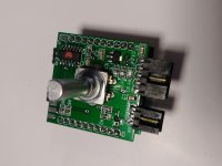
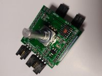
2. I'm also, assuming that this is the correct rotary encode PEC11L-4225F-S0015. If not what is the correct one?
3. Using the main board power supply just requires a transformer with two 15v to 18v secondaries?
Thanks for the help.
1. What is the remote control being used for the volume control.
2. I'm also, assuming that this is the correct rotary encode PEC11L-4225F-S0015. If not what is the correct one?
3. Using the main board power supply just requires a transformer with two 15v to 18v secondaries?
Thanks for the help.
1. many codes are supported, every remote control I checked (Phillips, Sony TV / Apple Remote / OneForAll / Samsung TV …)
2. I have no experience with this type but other users build there muses with this type
3. I prefer 3 secondaries. 2 >=15Vac for the analog / muses circuit and 1 ~8Vac for the control and relay circuit.
2. I have no experience with this type but other users build there muses with this type
3. I prefer 3 secondaries. 2 >=15Vac for the analog / muses circuit and 1 ~8Vac for the control and relay circuit.
I need a set up, how do I get one. I m in india
I need a relay selection and volume control so how do I go about.
I need a relay selection and volume control so how do I go about.
Thanks Daniel. I wouldn't be asking if it was clear to me—and not sure how anyone would build this awesome project without your fine documentation AND now Chris's most excellent V2 build guide (good images btw.). I always choose to post even the dumbest questions since you never know who might be on the fence with such a project, it's not simple, and maybe someone would benefit.
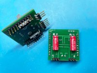
See attached pic. V1 documentation on left, V2 on right (J1 note states "Muses72320", should be 72323?). I thought I had read the schematic correctly, but now it seems that I've jumpered the wrong pads?—and am double-checking with the fine forum folks to make sure—looks like the schematic says R4 connects to pad/pin 3, and by that logic I've jumpered 2 and 1 (center and right pad). Would explain a lot I suppose since I have not a peep of audio from the unit, it's easy for a noob to read/imagine "1,2,3" across those J1 pads 🙂 even while looking at the schematic—surely it's just my brain though.
I haven't pulled out my V1 build since I got it all working again in the DCG3 preamp to see what pads I jumpered there (seeing as how it appears to be the same procedure between V1 and V2)....There's no silk on the V1 boards for those spots, so I probably just followed the drawing (not indicated on the V2 documentation)... Hopefully I've explained this mild confusion on my part...
Attachments

Pfarrell,
When you get yours worked out correctly, could you take some photos and post them? I am also a bit confused regarding precisely what is needed for the unbalanced control.
Thanks
When you get yours worked out correctly, could you take some photos and post them? I am also a bit confused regarding precisely what is needed for the unbalanced control.
Thanks
Your english is great—as is this project—and for that I'm massively grateful.
The issue is entirely my own—via lack of knowledge (and overly visually oriented)—I have no idea what percentage of knowledge-starved individuals I represent on DIY audio so I always assume the lowest end of who might be attempting DIY efforts. I believe we represent the ultimate in the search for "what's good for us", but I digress. Even with stuff I feel I know something about—I still keep in mind a "beginner's mindset". This keeps a constant state of learning in action, for me.
No, the instructions aren't clear—to me. Otherwise I'd have a working V2 and wouldn't have asked in the first place—I also might not have truly tried to understand the schematic—so, win win for me. If you had put the red jumper line on the V2 image, like the V1 image—I would have heard music (I think 😀). But then at least one person (aljordan, it seems) wouldn't have been helped either! I don't mind asking stupid/obvious questions in public. I have nothing to prove.
Last edited:

Pfarrell,
When you get yours worked out correctly, could you take some photos and post them? I am also a bit confused regarding precisely what is needed for the unbalanced control.
Thanks
Yes I will.
Thanks.
Documentation for this project was a lot of work.
The jumper in v1 must be set.
For v2, the jumper settings depends on user config.
This is the reason why I didn’t marked any position.
Daniel
Documentation for this project was a lot of work.
The jumper in v1 must be set.
For v2, the jumper settings depends on user config.
This is the reason why I didn’t marked any position.
Daniel
Well, another successful build to get the DCG3 back online (SO GOOD)... V1, since I had the parts sitting here. Apple remote programmed on second try—so effortless—thanks Daniel! (Jumper properly sorted....)
No idea why I'm not getting anything out of the V2 build, even after proper jumper setting... the faintest hair of audio coming out of the right speaker, but fuzzy—also no lighting of the LED. I guess there's something bad in it...I can't find any parts/soldering errors, but also haven't tried to really figure it out (I do know it's not the encoder since I took it for the new V1, and it's fine)—might be faster to build another V2 (SMD is super fun)—it seems diodes and regs are hard to come by right now—mini-MELP fit the diode pads?, seems like they just might based on the sheets? (I gambled $1.50 on this, so I can report back ;-). I did find another 72323 (both Mouser and Digikey US-side seem to have a few)....
I'll build another V2 and put it in a dual-mono BA2108, maybe with the whole switching array...
Attachments
I am looking to build a pre and this could be the perfect project, unfortunately there is no screen. I just cannot conceive a preamp without a screen anymore, led if from another age 😵
The previous version had that, that's why I stuck to it. I have two of these actually with adafruit led displays. I'm sure @meldano will get around putting a display to this one as well.I am looking to build a pre and this could be the perfect project, unfortunately there is no screen. I just cannot conceive a preamp without a screen anymore, led if from another age 😵
I'm addicted to volume indication and a lot more to remote control but then again there are guys here using the Khozmos manual switching volume control... oldtimers, we have to live along side them... 🙂