Hi Chris,
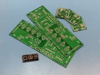
do you use the pre programmed controller? I can´t find a marker on the top.
Troubleshooting is always the same:
-3,3V power supply to the microcontoller
- connect status LED
- voltage on
- push the encoder button
If the LED toggle => everything with the controller is o.k.
do you use the pre programmed controller? I can´t find a marker on the top.
Troubleshooting is always the same:
-3,3V power supply to the microcontoller
- connect status LED
- voltage on
- push the encoder button
If the LED toggle => everything with the controller is o.k.
Yes sir. The marks came off while cleaning the boards. The voltages all appear to be good at the micro and elsewhere. No status LED light up, however. I presume the pull-up resistor additions were installed correctly and hopefully aren’t an issue. Both boards are acting the same, so perhaps they share a common problem.
Should I pick up a programmer and see if we can reach and possibly reprogram the microcontroller?
Should I pick up a programmer and see if we can reach and possibly reprogram the microcontroller?
Hi Chris,
do you use the pre programmed controller? I can´t find a marker on the top.
Troubleshooting is always the same:
-3,3V power supply to the microcontoller
- connect status LED
- voltage on
- push the encoder button
If the LED toggle => everything with the controller is o.k.
Attachments
Last edited:
Why reprogramming? The flash is not volatile.
Can you measure 3,3V at Vss / Vdd controller pins ?
Can you measure 3,3V at Vss / Vdd controller pins ?
Just throwing out options and reprogramming was one. Probably a dumb one.
I did have 3.3V on Vdd. Vss is shown as ground on the schematics, and I was reading zero there. I just lost my +15VDC regulator, so it looks like I've got a little more work to do now. 🙁
I'll wait until my new 15V transformer comes in before I do anything else. And get some new regulators on order.
I did have 3.3V on Vdd. Vss is shown as ground on the schematics, and I was reading zero there. I just lost my +15VDC regulator, so it looks like I've got a little more work to do now. 🙁
I'll wait until my new 15V transformer comes in before I do anything else. And get some new regulators on order.
any chance this would work with +- 12V ?? if so I have some regulators for you
EDIT - based on data sheet for 7230 chip ( is this still the right chip ? = NO 7232 is the new one ) it can function from +-8.5 to +-18V
7232 data sheet indicates +- 10 to +- 18
@meldano - if 12V will work, I can save Chris the wait for shipping
EDIT - based on data sheet for 7230 chip ( is this still the right chip ? = NO 7232 is the new one ) it can function from +-8.5 to +-18V
7232 data sheet indicates +- 10 to +- 18
@meldano - if 12V will work, I can save Chris the wait for shipping
Last edited:
Thanks dB. AFAIK, the +/-15V is for the Muses chip (72323 is current). The CPU runs on +3.3V which I have (had until a few minutes ago). The +/- limits the input swing on the Muses, which may not be a big deal. Might be worth trying if it's compatible. The +12V will feed the +3.3V reg without issue, I suspect. Appreciate your generosity!
I may consider putting those regs on heatsinks, too. But I can't sense any significant heat coming from them. :shrug:
I may consider putting those regs on heatsinks, too. But I can't sense any significant heat coming from them. :shrug:
any chance this would work with +- 12V ?? if so I have some regulators for you
EDIT - based on data sheet for 7230 chip ( is this still the right chip ? = NO 7232 is the new one ) it can function from +-8.5 to +-18V
7232 data sheet indicates +- 10 to +- 18
@meldano - if 12V will work, I can save Chris the wait for shipping
Last edited:
Chris,
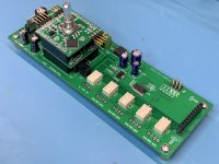
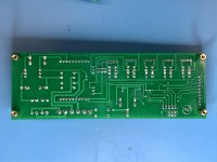
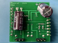
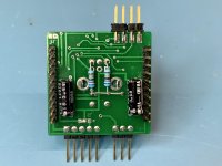
please post a big high res pic from all boards (top/bottom), not that you put a solder jumper to wrong place.
meldano's doc is really good but sometimes (as me) I make a little mistake an then the looking goes crazy.
please post a big high res pic from all boards (top/bottom), not that you put a solder jumper to wrong place.
meldano's doc is really good but sometimes (as me) I make a little mistake an then the looking goes crazy.
Thanks Carsten. Let’s start with the unbalanced set.
Attachments
-
 8C979E1D-F134-4957-9DD1-AA1662A2C0F1.jpg791.2 KB · Views: 266
 -
 4FE1F2AB-46FD-4939-BBD3-B94603DC8989.jpg962.3 KB · Views: 261
 -
 489CF582-1A91-4D2C-AAA4-9E935DE1E71A.jpg653.5 KB · Views: 256
 -
 577EC2A1-B64E-41D1-861D-3A65B0EB9CEC.jpg717.5 KB · Views: 243
 -
 405F4813-B80B-4460-84B1-1A44C0DCEEF3.jpg676.2 KB · Views: 163
 -
 6BC6D1AF-4D34-428E-B1C1-4EF3730241FD.jpg751.9 KB · Views: 157
 -
 6D8C14AA-BDA2-4A6C-BD80-D426BB3EE5D5.jpg878.6 KB · Views: 152
 -
 45C85CF6-21B0-4A00-A65C-0ACF608E1BA9.jpg903.6 KB · Views: 204
 -
 82AEC325-7C96-43A0-82FD-3107A90981D5.jpg750.8 KB · Views: 165
No worries. I have no doubt. 🙂 Just scratching my head on this one and reaching for possibilities.
I double checked every controller before shipping
Chris,
I didn't see what can be wrong, so eagle eye meldano should look also to your boards. :-(
I didn't see what can be wrong, so eagle eye meldano should look also to your boards. :-(
Thanks for looking. 
Chris,
I didn't see what can be wrong, so eagle eye meldano should look also to your boards. :-(
Good news! After re-reading the adjustment procedures, it turns out I’m just slightly blind and impatient. 😛
The status LED is quite dim with the suggested 2K resistor, so I just hadn’t noticed it blinking at me. I watched closely as I powered up holding down the encoder button, and I also didn’t wait long enough for it to signal me. It works as expected and the remote control and parameter tables program as designed. So the micro is good! What a relief.
I still have a bad -15V regulator, and those are on order (or in transit from dB-Key 😀 - thanks dB!)
I’ll see what other features I can test with positive voltage only.
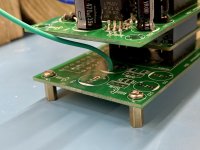
Oh, although it worked without it, I also provided a proper ground from my secondary main board on the balanced set since there were plenty of holes available from which to choose. We’ll see if it’s a noise generator and if I’ll need to move it closer to the power source entry point.
The status LED is quite dim with the suggested 2K resistor, so I just hadn’t noticed it blinking at me. I watched closely as I powered up holding down the encoder button, and I also didn’t wait long enough for it to signal me. It works as expected and the remote control and parameter tables program as designed. So the micro is good! What a relief.
I still have a bad -15V regulator, and those are on order (or in transit from dB-Key 😀 - thanks dB!)
I’ll see what other features I can test with positive voltage only.
Oh, although it worked without it, I also provided a proper ground from my secondary main board on the balanced set since there were plenty of holes available from which to choose. We’ll see if it’s a noise generator and if I’ll need to move it closer to the power source entry point.
Attachments
Last edited:
I presume the Muses controls the relay driver on the main board which is why it's not doing anything since I'm down a power supply rail at the moment. All outputs read +5V, so I presume that chip provides an active low to drive relays and LEDs.
I am relieved 😉
Relays:
Did you set the parameter
4, Max Input >0 and restart?
Yes, the driver provides an active low to drive the relays.
Have a look to the schematic.
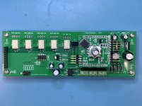
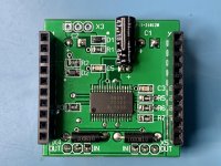
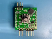
Controller Board J2:
Set the jumper to 2:3 because 3,3V supply from mainboard is connected.
LED:
I will remove the value. It was only an example.
Relays:
Did you set the parameter
4, Max Input >0 and restart?
Yes, the driver provides an active low to drive the relays.
Have a look to the schematic.
Controller Board J2:
Set the jumper to 2:3 because 3,3V supply from mainboard is connected.
LED:
I will remove the value. It was only an example.
Last edited:
We share similar relief!
I did not set that parameter. I left everything defaulted first go around. I’ll double check that setting.
Your schematics are great. Thanks for the detail! I’ll update the jumper position and report back when I get the regs installed.
After a second thought about the ground I installed for testing, it will likely be grounded through the audio ground of the stage it connects to. Probably going to introduce a ground loop like this. I'll take it off when installing it in its home gear.
Appreciate your support!
Edit: After inspecting pictures, the jumper on the micro board should be in the correct position. The board is upside down in the photo. 🙂 I’ll still double check, though.
I am relieved 😉
Relays:
Did you set the parameter
4, Max Input >0 and restart?
Yes, the driver provides an active low to drive the relays.
Have a look to the schematic.
Controller Board J2:
Set the jumper to 2:3 because 3,3V supply from mainboard is connected.
LED:
I will remove the value. It was only an example.
Last edited:
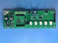
I see the controller board and programmed u-controller, but where can I find the mainboard?
I haven't read the entire thread, so I may have missed that info.
I haven't read the entire thread, so I may have missed that info.
Are you looking for a photo of it or something different? There are some front/back photos in post #550. It contains a PSU and input switching.
I see the controller board and programmed u-controller, but where can I find the mainboard?
I haven't read the entire thread, so I may have missed that info.
Last edited: