What signal do you see (strong signal driven into the RCA jacks) on the preamp board jumpers, on pins 1 and 7 of the 5532 closest to the optocouplers?
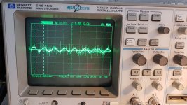
Photo 1 is the signal present on the jumper.
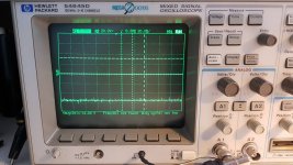
Photo 2 is the signal present on NE5532 Pin1 and Pin7 closest to the optocoupler. There is no audio present on any of the pins
The other NE5532 has a audio sine wave on the optocouplers Pin1 and Pin7
Photo 2 is the signal present on NE5532 Pin1 and Pin7 closest to the optocoupler. There is no audio present on any of the pins
The other NE5532 has a audio sine wave on the optocouplers Pin1 and Pin7
Attachments
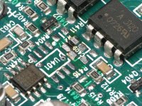
I found a photo showing the op-amp closest to the optocouplers as U401. I'm going to refer to the first op-amp as U400.
U400, pin 7 drives U401 pin 3. If you don't see audio on U401, pin 3, post the DC voltage on all terminals of U401.
Pin 1:
Pin 2:
Pin 3:
Pin 4:
Pin 5:
Pin 6:
Pin 7:
Pin 8:
U400, pin 7 drives U401 pin 3. If you don't see audio on U401, pin 3, post the DC voltage on all terminals of U401.
Pin 1:
Pin 2:
Pin 3:
Pin 4:
Pin 5:
Pin 6:
Pin 7:
Pin 8:
I cant see any NE5532 marking numbers on the PCB, so I measured both.
NE5532 closest to the optocoupler:
Pin 1: -13.88v DC
Pin 2: 1.194v DC
Pin 3: 0.7v DC
Pin 4: -15.44v DC
Pin 5: -12.55v DC
Pin 6: -11.60v DC
Pin 7: -14.07v DC
Pin 8: 15.44v DC
Other NE5532:
Pin 1: audio signal (about 1.4v Peak to peak)
Pin 2: audio signal (about 0.8v peak to peak)
Pin 3: audio signal (about 0.8v peak to peak
Pin 4: -15.44v DC
Pin 5: audio signal (about 0.8v peak to peak
Pin 6: audio signal (about 0.8v peak to peak)
Pin 7: audio signal (about 1.4v peak to peak)
Pin 8: 15.44v DC
U401 Pin2 and Pin3 pads also dont have a sine wave on it.
U400 Pin1 and Pin7 is a sine wave output.
U400 Pin1 and Pin7 is a sine wave output.
There are two 2k resistors between those pins on those two op-amps. Confirm that they're within tolerance.
Confirmed. Within tolerance
Both of those resistors have the sine wave output from U400 on each side
Both of those resistors have the sine wave output from U400 on each side
They are connected between U401 Pin2/ Pin3 and U400 Pin1/Pin7
Looks like the sine wave is getting drained down at U401 Pin2 and Pin3 pads (Pin2 and Pin3 are still disconnected)
3.65Kohm between U401 Pin2 and GND.
3.3Kohm between U401 Pin3 and GND.
Looks like the sine wave is getting drained down at U401 Pin2 and Pin3 pads (Pin2 and Pin3 are still disconnected)
3.65Kohm between U401 Pin2 and GND.
3.3Kohm between U401 Pin3 and GND.
No, both resistors have a signal at only 1 side of the resistors.
The side of the resistor with a signal is the side connected to U400 Pin1 and Pin7
The other side of the resistors (connected to U401 Pin2 and Pin3) have no signal
The side of the resistor with a signal is the side connected to U400 Pin1 and Pin7
The other side of the resistors (connected to U401 Pin2 and Pin3) have no signal
Between the output terminals of U400 and the corresponding input terminals of U401, do you read 2k? Place the meter probes directly on the terminals of the op-amps.
I read 1.7K between the U400 output and U401 input pads.
The resistors from 2K in between read within tolerance, they read 1995ohm.
The resistors from 2K in between read within tolerance, they read 1995ohm.
If you can easily remove U401, do so and confirm that you get signal on the input terminals of U401.
Also measure the resistance again to confirm that it's the same as the resistor value.
Measure across the two input pads and post that value as well.
Also measure the resistance again to confirm that it's the same as the resistor value.
Measure across the two input pads and post that value as well.
All values read the same with U401 removed.
No audio signal measurable on any of the U401 pads.
7Kohm between U401 input pads.
No audio signal measurable on any of the U401 pads.
7Kohm between U401 input pads.
- Home
- General Interest
- Car Audio
- MTX Thunder 81001 component value/schematics