Reinstall the op-amp (a new one if you have one) to see if you get output from pin 1 with the diode out of the circuit.
I don't know what could be happening to the signal. The input impedance to that op-amp is in the mega-ohm range.
Yes, that is true. A very high impedance between U401 Pin2 and Pin3 out of the circuit.
It's about 0.8Mohm
It's about 0.8Mohm
Maybe this has something to do with it.
U400 Pin1 and Pin7 output sine wave has 0v as DC voltage with a Utop of 450mV (P-P voltage is 900Mv)
U401 input Pin2 is a flat 1.15v DC voltage
U401 input Pin3 is a flat 0.53v DC voltage
U400 Pin1 and Pin7 output sine wave has 0v as DC voltage with a Utop of 450mV (P-P voltage is 900Mv)
U401 input Pin2 is a flat 1.15v DC voltage
U401 input Pin3 is a flat 0.53v DC voltage
Last edited:
The input terminals 2 and 3 of U401 should be identical to the outputs of U400. If you touch the board around this area (not on a trace or pad), does the scope deflect any?
Sorry, I don't know excactly what you mean.
Should I trace U401 Pin2 or Pin3 while touching the PCB? And look for bumps in the voltage?
Should I trace U401 Pin2 or Pin3 while touching the PCB? And look for bumps in the voltage?
I'm looking for leakage/contamination on the board. If there is something like leaked electrolyte, the trace will deflect when touching nothing more than the board.
I could not measure any deflections when touching the board on several places around that area.
I have also cleaned the board with isopropyl after soldering.
I have also cleaned the board with isopropyl after soldering.
Yes, one side is connected to GND.
I found a critical thing.
The offset at U401 Pin2 and Pin3 explained in #110 is not supposed to be there I think.
I used an other device which can give a little stronger RCA signal. There was a low duty-cycle PWM signal at the optocouplers input.
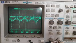
The first photo is a sine wave (U400 Pin1 and Pin7), and the DC line is U401 Pin2.
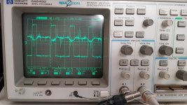
IF the Utop from U400 Pin1 and Pin7 is rising above the DC offset at U401 Pin2, it starts to oscillate at the optocoupler (photo 2).
The strange wave is the signal at U401 Pin2 in that case.
So, signals above the DC offset from U401 starts to result in a pwm output. Directly explains why the dutcy cycle is so low.
Means that the DC offset at U401 Pin2 and Pin3 needs to be eliminated
I found a critical thing.
The offset at U401 Pin2 and Pin3 explained in #110 is not supposed to be there I think.
I used an other device which can give a little stronger RCA signal. There was a low duty-cycle PWM signal at the optocouplers input.
The first photo is a sine wave (U400 Pin1 and Pin7), and the DC line is U401 Pin2.
IF the Utop from U400 Pin1 and Pin7 is rising above the DC offset at U401 Pin2, it starts to oscillate at the optocoupler (photo 2).
The strange wave is the signal at U401 Pin2 in that case.
So, signals above the DC offset from U401 starts to result in a pwm output. Directly explains why the dutcy cycle is so low.
Means that the DC offset at U401 Pin2 and Pin3 needs to be eliminated
Attachments
- Home
- General Interest
- Car Audio
- MTX Thunder 81001 component value/schematics