I re-measured.
I think the connector of the separate filter board was plugged out for a part, readings are different now. Seems like the filter board influences a lot in this kind of mtx amplifiers.
There still is a 1k resistor and a jumper between 7805 regulator GND and C118-
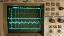
C118- reads strange triangle wave - 15.76v
FET191:
Pin1: -6.66v strange wave
Pin2: 82v rail
Pin3: -0.5v same triangle wave as C118-
Both NE5532 output section.
Between Pin4 and Pin8 reads 30.5v and are still heating up.
Red LED400 and LED401 are still burning red.
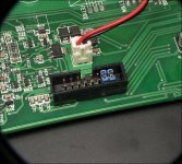
In the photo attached is C118-
I think the connector of the separate filter board was plugged out for a part, readings are different now. Seems like the filter board influences a lot in this kind of mtx amplifiers.
There still is a 1k resistor and a jumper between 7805 regulator GND and C118-
C118- reads strange triangle wave - 15.76v
FET191:
Pin1: -6.66v strange wave
Pin2: 82v rail
Pin3: -0.5v same triangle wave as C118-
Both NE5532 output section.
Between Pin4 and Pin8 reads 30.5v and are still heating up.
Red LED400 and LED401 are still burning red.
In the photo attached is C118-
Attachments
Jumper resistor between 7805 GND and C118- is now 1.8ohm.
Resistor does not heat up.
C118- now measures 0v (GND).
Fet191:
Pin 1: 18.47v
Pin 2: 82v rail
Pin 3: 15.36v
NE5532
Pin 4: -15.2v
Pin 8: 15.3v
They also barely heat up anymore. Which is strange, because the voltage across Pin4 and Pin8 has not changed. There is no wave coming in or out the NE5532.
LED400 and LED401 are still on (red colour).
They aren't heating because they aren't switching, most likely.
Does anything change if you drive a signal into the amplifier?
Does anything change if you drive a signal into the amplifier?
First the NE5332 overheated, they became burning hot.
This was before the 1.8ohm resistor was placed to ground C118 -
After placing the resistor the 5532 now run cool, while the voltage on Pin4 and Pin8 has not changed. Happy they run cool now, but it's strange.
Like there would be a high voltage on any other pins maybe?
There is no signal on any of the NE5532 pins. The error LED's 400 and 401 are still on.
Do you know where the signal of the NE5532's should be coming from? And what signal is triggering the error lights to come on?
I removed the 1.8 ohm resistor to check the voltages on the 5532, and yes there are voltages from -55v present (the same 30v potential difference between Pin4 and Pin8)
With resistor the maximum is +-15v present. So that could explain a lot why they overheat.
Last edited:
I just can't figure it out with this amp. Is there someone who can help me out with this one?
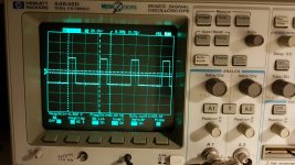
Placing the jumpers does not result in a square wave on the NE5532.
Placing the jumpers does not result in a square wave on the NE5532.
Nothing has changed. The amp had been layed down on the shelf for 1.5 month. Due tue personal matters I could not find time to repair amps.
Took it of the shelf this weekend, and boom, square wave gone. Tried to find the source of the output pwm generation, but I get no square wave activities out of it.
Also not with the jumpers and audio signal on the RCA.
Took it of the shelf this weekend, and boom, square wave gone. Tried to find the source of the output pwm generation, but I get no square wave activities out of it.
Also not with the jumpers and audio signal on the RCA.
Perry, do you know what signal should be present on the jumper pins?
I'm talking about the pins that should be connected with a jumper wire to bypass the filter board.
I'm talking about the pins that should be connected with a jumper wire to bypass the filter board.
Strange. There is audio present on both jumper wires.
FET191 and the NE5532 have the same readings as before.
FET191 and the NE5532 have the same readings as before.
- Home
- General Interest
- Car Audio
- MTX Thunder 81001 component value/schematics