MTM is different On-axis!
Restate comment- MTM and TM have equal Flatness on-axis but MTM sounds different than TW
I didn't want to let this go unanswered, but a proper answer is beyond the scope of a post. I did a quick and dirty mockup to help make a point.When using a waveguide (e.g. 12” wide 90x60 dispersion), which topology would result in the most uniform dispersion between M and T?
I've assumed your waveguide was 12" tall as well. Sometimes it is assumed that a narrow vertical pattern gives a shorter looking waveguide but optimising the mouth requires further investigation.
Looking at the first attachment, where I have set a wavelength equal to the size of the woofer, the radiation appears to be not far from 60 degrees.
Interference appears to be playing a part in this. I had an example prepared for my earlier post (second attachment) where I curved the source. The radiation appears to be slightly more wide. I'd put this not to the source pushing wider, but to a reduction of HOM.
Attachments


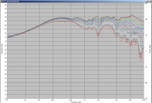
I'll join adason in posting polars of my MTM 🙂 (horizontal, no vertical) edit: the steps are 10deg
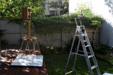
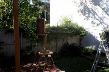
The pictures show the test setup when taking them. Not ideal and I do need to come up with a better system.
From 270Hz down they are actively crossed to a couple of Vifa M26WR09-08's The design goal was never for them to have bass extension.
The crossover frequency is (horror of horrors) 2.8Khz fourth order bessel (acoustic). Which coincidentally (even more horror) is exactly 1 wavelength based on the CTC distance between mid and tweeter of 122mm...
The important bit is that the wife thinks that they sound far superior to anything she has been able to audition at the local hifi shop (she didn't particularly like the look of my speakers), and as a result I got the blessing that provided I keep things at least somewhat waf friendly looks wise I'm free to keep doing diy 😉
Tony.
Attachments
Last edited:
Measurement graphs are always interesting to watch, and i can see that the area between 2-5khz is a bit hot, have you tried to decrease this output?
Yes it is interesting, that particular measurement is not characteristic of most of the measurements I have done, it is normally a bit hot between 1 and 2Khz, and there is actually a notch there, and on reviewing this one I was thinking that that notch could be reduced.
I took full 180 deg horizontals of each of the three drivers with the intention to do a new crossover, but I found some anomalies in the measurements and was going to re-do (that was about two years ago) and I still haven't done so. I need to make a better turntable as this one gets unstable post about 100 deg, also need a bit bigger space!!
Attached is a graph showing a different measurement with a sim of a new crossover I did a few years ago (but never got around to implementing) Not even sure I can find that particular version. I believe that should have been the same crossover, so I'm not sure what happened the day I did the polars, as I normally get very consistent measurements.
I did more measurements later of the individual drivers for the polars but not of the speaker, I suspect there may have been something wrong that day.
If I do a new crossover, I'm going to try and get a bit more efficiency these have close to full baffle step comp factored in and have a hot spot in room around 500Hz.
Tony.
Attachments

Hi hifijim,
I can only offer anecdotal observations, but I do have a pair of MTMs that I think turned out nice. Augerpro mentioned Lynn Olson’s Ariel. I combined a deep tower cabinet for the two subs (NHT1259) and grafted a sealed interpretation of Mr. Olson’s ME2 which was just a scaled down version of the transmission line Ariel.
Mr. Olson goes to great lengths discussing golden section ratios and now that informed the driver placement. If you’re interested in theory, his Nutshell HiFi website appears to have everything that he published in his book “The Soul of Sound”.
The other thing I’d like to pass on is the woofer size. You mentioned something between 5-6 inches. I’ve been advised more than once that getting the mid-range and vocal portion of the sound spectrum is the most critical. If you convince your brain that those are accurate, the rest just sort of falls into place (apologies to the “if I can’t measure it, it doesn’t exist” folks for the psychoacoustics babble). This pointed more toward the 5” woofer. Sadly, the Vifa P13WH is long since discontinued.
I sat in a mostly centered location and the ceiling was angled, so perhaps I just didn’t run into some of the more serious flaws that a MTM can exhibit.
Good luck with your project.
Just brain fart’n here but would one of these newer coaxial cd/horn alleviate the higher crossover problem in a (Say 10”) mtm.......or would that not even be Considered mtm anymore?
here is my vifa mtm, with amt tweeters, the most neutral speakers i made so far
Impressive measurements. Very interesting.
What's the xo point, slope and type you use? I imagine math would tell significant lobing is to be expected. What's your experience? Do you have treated ceiling?
Adason,
I went through the 5 pages, but didn't see the info. There's a reference to 300 and 3000Hz but for another mtm.
I went through the 5 pages, but didn't see the info. There's a reference to 300 and 3000Hz but for another mtm.
All I found was in two places he said it's just a 4.5 uF cap, so 1st order, though found no mention as to actual frequency.
GM
GM
vifas have no crossover at all, because when I used coil, phase went to hell
they naturally start rolling of at ~5kHz, so I experimented with the cap (the only crossover element in the whole mtm), and ended up with 4.5uF, so crossover point would be around 7-8kHz, first order on tweeter
all based on measurements and listening
they naturally start rolling of at ~5kHz, so I experimented with the cap (the only crossover element in the whole mtm), and ended up with 4.5uF, so crossover point would be around 7-8kHz, first order on tweeter
all based on measurements and listening
here is my 'dirty' room mtm top...two 6fe200 in series, yes, amp friendly 16 ohm, and big HiVi planar with just one cap from 5kHz
15" woofers, all biamped
flat, dynamic, efficient, easy to drive, brutally loud, yet clean
Adason,
Sorry my first post wasn't clear. I was asking about xo ppoint, type, order for the MTM with 6FE200 and HiVi planars.
I'm working with a large AMT and two 8 inchers, so I'm interested in your rexperience with 6" and HiVi.
I didn't want to let this go unanswered, but a proper answer is beyond the scope of a post. I did a quick and dirty mockup to help make a point.
I've assumed your waveguide was 12" tall as well. Sometimes it is assumed that a narrow vertical pattern gives a shorter looking waveguide but optimising the mouth requires further investigation.
Looking at the first attachment, where I have set a wavelength equal to the size of the woofer, the radiation appears to be not far from 60 degrees.
Interference appears to be playing a part in this. I had an example prepared for my earlier post (second attachment) where I curved the source. The radiation appears to be slightly more wide. I'd put this not to the source pushing wider, but to a reduction of HOM.
Thanks, Allen. The height of a 12” wide 90x60 waveguide is typically 6-7”.
But more importantly, which of the four woofer configurations (1-4) around the WG results in the most uniform directivity?
how about this layout?
I am at the early stages of learning in this hobby but I wonder why the tweeter array is always set up with a single tweeter at 12 and 6 o'clock instead of rotating the array so that two tweeters are at the 6 and 12 position so you can minimize center to center spacing. Is center to center spacing not that important or is it just an aesthetic thing or does changing the pattern change something else that I'm not aware of. Like I said, I'm a noob and just want to learn. Thanks.
Adason,
Sorry my first post wasn't clear. I was asking about xo ppoint, type, order for the MTM with 6FE200 and HiVi planars.
I'm working with a large AMT and two 8 inchers, so I'm interested in your rexperience with 6" and HiVi.
Well, in my opinion, my crossover, slopes, frequencies and so on, are completely irrelevant to your mtm with 8" midbasses and large AMT.
Crossover depends when your 8" starts beaming, how severe the breakups are, what slope you need to take care of those, and how low can your tweeter go.
It's all specific to your application.
I select midbass with the minimum breakups, ideally none, or so little that I can tolerate it, then measure off axis behavior, and then decide where to cross.
You need to measure to know. To know is to measure. I do not shimulate 🙂
Good luck!
I am at the early stages of learning in this hobby but I wonder why the tweeter array is always set up with a single tweeter at 12 and 6 o'clock instead of rotating the array so that two tweeters are at the 6 and 12 position so you can minimize center to center spacing. Is center to center spacing not that important or is it just an aesthetic thing or does changing the pattern change something else that I'm not aware of. Like I said, I'm a noob and just want to learn. Thanks.
Its discussed here:
Help Understanding Tekton Tweeter Array Schematic?
Well, in my opinion, my crossover, slopes, frequencies and so on, are completely irrelevant to your mtm with 8" midbasses and large AMT.
Crossover depends when your 8" starts beaming, how severe the breakups are, what slope you need to take care of those, and how low can your tweeter go.
It's all specific to your application.
I select midbass with the minimum breakups, ideally none, or so little that I can tolerate it, then measure off axis behavior, and then decide where to cross.
You need to measure to know. To know is to measure. I do not shimulate 🙂
Good luck!
I wasn't trying to simulate, but to draw conclusions from more experienced folks. Most times such folks are generous sharing their wisdom.
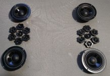
Here are some measurements I took. TPL-150H plus two 8PE21 in MTM. Measured the TPL alone, then the the twin 8" alone. Horizontal and vertical.
Where do you think I should xo them at, slope? What do you think of the vertical dispersion?
Attachments
-
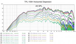 TPL-150H horizontal dispersion.jpg228.5 KB · Views: 301
 -
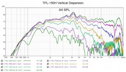 TPL-150H vertical dispersion.jpg206.1 KB · Views: 289
 -
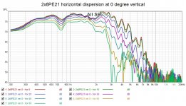 2x8PE21 horizontal dispersion at 0 degree vertical.jpg189 KB · Views: 279
 -
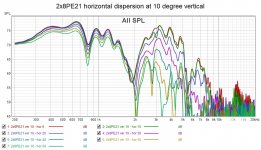 2x8PE21 horizontal dispersion at 10 degree vertical.jpg196.3 KB · Views: 288
 -
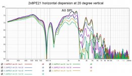 2x8PE21 horizontal dispersion at 20 degree vertical.jpg192.1 KB · Views: 140
 -
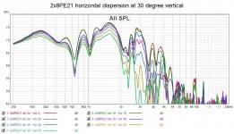 2x8PE21 horizontal dispersion at 30 degree vertical.jpg191.8 KB · Views: 127
 -
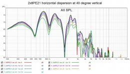 2x8PE21 horizontal dispersion at 40 degree vertical.jpg183.1 KB · Views: 132
- Home
- Loudspeakers
- Multi-Way
- MTM sound characteristics