Have You by chance taken a look at the SOT23 FMMT617/717 from Zetex?
Their Spice Models show very low Rbe values.
Hi, Calvin
Very interesting circuits, thanks.
The spice models from zetex transistors always have very low base resistance, for example the bc817 have 2.5 ohms and the bc848c only 6 ohms, that is very different from the real devices.
I am thinking why i get more distortion with the " New " Zetex.
Sergio sugested it could be the high input capacitance.
I do not think so because i use a 1kOhm / 6 Ohm voltage devider at the input when i measure this circuits.
With 6 Ohm source resistance capacitive loading should have minimal effect.
The voltage devider is also nesessary to reduce the noise in the measurements.
I have that trick from Douglas Self.
He even uses 1 Ohm but i wanted to mimic my Titan cartridge that has 5.5 Ohm.
Last edited:
Preamp from 11-12/1986
I rebuilt that Elektor design with 627's (when they became available around '91), with a completely external beefed-up power supply.
Even standard, not half bad, in particular for Elektor stuff.(pricey to build though)
At the time, not yet able to manufacture such pretty boards myself.
(Courtesy of AD, ch 7, you must have a very early edition)
Last edited:
I found an interesting link, also about headphone amplifiers.
It shows various distortion mechanisms and compensating methods.
Unfortunately it contains very litttle circuit diagrams.
http://www-3.unipv.it/dottMICR/tesi/Lollio.pdf
It shows various distortion mechanisms and compensating methods.
Unfortunately it contains very litttle circuit diagrams.
http://www-3.unipv.it/dottMICR/tesi/Lollio.pdf
Sergio sugested it could be the high input capacitance.
I do not think so because i use a 1kOhm / 6 Ohm voltage devider at the input when i measure this circuits.
With 6 Ohm source resistance capacitive loading should have minimal effect.
The voltage devider is also nesessary to reduce the noise in the measurements.
I have that trick from Douglas Self.
He even uses 1 Ohm but i wanted to mimic my Titan cartridge that has 5.5 Ohm.
It was not me 🙂 , but I agree with Calvin.
The non linear parasitic capacitances may be the reason for the increase of the thd.
It is not only the source impedance that matters, the output impedance of your input circuit is also important. What is the value of the resistor connected to the collector of your input transistor?
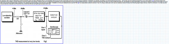
I wanted to explain my substitution method a little better.
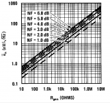
Here is an older but still valid apllication note about noise :http://materias.fi.uba.ar/6648/archivos/AN-104.pdf
You can see that the noise of the preamplifier must be around 0.4nV / qHz ( shorted )
over a 20Hz to 20kHz bandwidth when an inplugged 10 Ohm resistor gives a worcening of 3dB.
Here is an older but still valid apllication note about noise :http://materias.fi.uba.ar/6648/archivos/AN-104.pdf
You can see that the noise of the preamplifier must be around 0.4nV / qHz ( shorted )
over a 20Hz to 20kHz bandwidth when an inplugged 10 Ohm resistor gives a worcening of 3dB.
Attachments
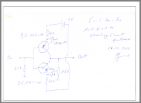
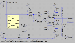
It is a parallel symmetric open loop design that is summed at the collectors ( PNP, NPN tied together ) with 160 Ohm to ground.
The transistors have 3.3 Ohm emitter resistors.
Input resistors are 300 Ohm to ground.
The transistors have 3.3 Ohm emitter resistors.
Input resistors are 300 Ohm to ground.
This is in priciple the circuit i use.
I added a CCS in series with the battery and made a balanced input.
Sorry, i can not disclose all the details this time.
There was design input from several people and a lot of know how exchange but in principle the circuit shown does the job.
Maybe some of you have a better idea.
I added a CCS in series with the battery and made a balanced input.
Sorry, i can not disclose all the details this time.
There was design input from several people and a lot of know how exchange but in principle the circuit shown does the job.
Maybe some of you have a better idea.
Attachments
That is where we live :https://www.youtube.com/watch?feature=player_embedded&v=rENyyRwxpHo
I think it is beautifull.
Thinking that we fall into the Great Attractor is not a such nice thought though.
Maybe the sun is a neutron star by then anyway.
I think it is beautifull.
Thinking that we fall into the Great Attractor is not a such nice thought though.
Maybe the sun is a neutron star by then anyway.
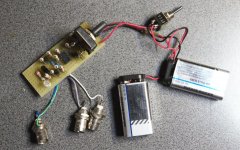
Today the ATL electronics specialist paid me a visit, and they had a present. The unit that they gave away is called an 'IGC' (or in our usual lingo an 'In-Circuit General-Purpose Curve-Tracer). The unit is battery powered, and exposes 3 B&C connectors.
1: Black/White = D.U.T.
2: Purple/Gray = Scope(X)
3: Green/Blue = Scope(Y)
The tester can be used to compare two circuits (one working and one that lost some of it's smoke), differences between the two circuits are visible through different traces that are displayed. This I.G.C. tester can very quickly pinpoint components or circuit parts where faults may be located.
The maximum voltages and currents that are injected in the DUT are
1mA +/-
5V +/1
This is safe for most (if not all) circuits.
Attachments
I have started a new thread for this tester.
http://www.diyaudio.com/forums/equi...general-purpose-curve-tracer.html#post4070420
Also: I simplified the schema slightly 🙂
http://www.diyaudio.com/forums/equi...general-purpose-curve-tracer.html#post4070420
Also: I simplified the schema slightly 🙂
Today the ATL electronics specialist paid me a visit, and they had a present. The unit that they gave away is called an 'IGC' (or in our usual lingo an 'In-Circuit General-Purpose Curve-Tracer). The unit is battery powered, and exposes 3 B&C connectors.
1: Black/White = D.U.T.
2: Purple/Gray = Scope(X)
3: Green/Blue = Scope(Y)
The tester can be used to compare two circuits (one working and one that lost some of it's smoke), differences between the two circuits are visible through different traces that are displayed. This I.G.C. tester can very quickly pinpoint components or circuit parts where faults may be located.
The maximum voltages and currents that are injected in the DUT are
1mA +/-
5V +/1
This is safe for most (if not all) circuits.
It is a parallel symmetric open loop design that is summed at the collectors ( PNP, NPN tied together ) with 160 Ohm to ground.
The transistors have 3.3 Ohm emitter resistors.
Input resistors are 300 Ohm to ground.
Distortion:
It's the C from cb ... esp the differential C that doesnt cancel completely.
THx-RNMarsh
Give thanks that you have a choise.... to use HD downloads off masters - uncompressed and not messed with.
THx-RNMarsh