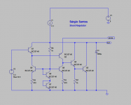
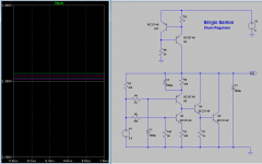
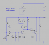
With decent temperature compensation
,and using the Frans idea of connecting the reference to the output.
🙂
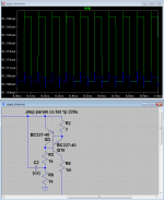
And here is an idea for a improved CCS, R8 is the current sensor, there is a 200mVpp 10Khz square-wave injected. The graph shows Green=1p Blue=220u capacitor
Attachments
Last edited:
TL431 for V2? BC550C for Q4 may improve Zout.
What happens when you add ESL and ESR and local decoupling?
What happens when you add ESL and ESR and local decoupling?
TL431 for V2? BC550C for Q4 may improve Zout.
What happens when you add ESL and ESR and local decoupling?
you can use another voltage reference , the tl431 is a little noisy.
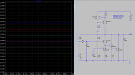
the output impedance depends of the open loop gain of the power supply, and as it is in post #9146 is already a bit high for my liking, so I eliminate cap C4, and add a small 220p cap in the base to collector of Q4, like that the Zout is 2miliR
The ESR of the output capacitor should be between 20mili and 200mili.
But is better to wait until test in real life.
This is the open loop gain and phase margin
Attachments

Lets see, Sergio is known to learn fast.
My wife says lots of times that i never learn. 🙂
Don't you just love it when everything work as planned ? 🙂
Ok , I have made a prototype of the shunt in a breadboard, and as planned the output voltage is 3.3 volts without temperature variations (tested with a hairdrier), the power supply is stable with only a 100nf cap, tested also with some bigger caps and no problems, even with the 1000uf cap in parallel with R8.
If I have time tomorrow I will design a board to test it better.
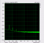
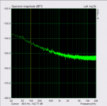
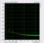
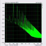
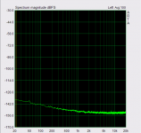
This test was made with only a cap of 33uf at the output, with a bigger cap the results are equal
1º picture is my emu1212m noise ground,
2º noise at the input of power supply,
3º is noise at the output without the 1000uf in parallel with R8.
4º is noise at the output with the 1000uf in parallel with R8.
5º is noise at the output without the 1000uf of the tl431 filter,
Ok , I have made a prototype of the shunt in a breadboard, and as planned the output voltage is 3.3 volts without temperature variations (tested with a hairdrier), the power supply is stable with only a 100nf cap, tested also with some bigger caps and no problems, even with the 1000uf cap in parallel with R8.
If I have time tomorrow I will design a board to test it better.
This test was made with only a cap of 33uf at the output, with a bigger cap the results are equal
1º picture is my emu1212m noise ground,
2º noise at the input of power supply,
3º is noise at the output without the 1000uf in parallel with R8.
4º is noise at the output with the 1000uf in parallel with R8.
5º is noise at the output without the 1000uf of the tl431 filter,
Attachments
Last edited:
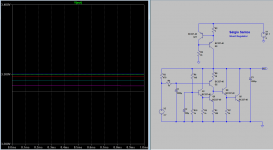
Forgot to say that i use a DN2540 (95ma) for the current source , this mosfet is a bitt noisy .
, and the tests was made with a 100 ohms resistor as load and also without load.
Using the tl431 with a simple filter is enough to get very low noise power supply.
the psrr at 100Hz is better than 120db.
The version with the cap in parallel with R8 have less noise than I can measure with my emu1212.
Last edited:
Don't you just love it when everything work as planned ? 🙂
Ok , I have made a prototype of the shunt in a breadboard, and as planned the output voltage is 3.3 volts without temperature variations (tested with a hairdrier), the power supply is stable with only a 100nf cap, tested also with some bigger caps and no problems, even with the 1000uf cap in parallel with R8.
If I have time tomorrow I will design a board to test it better.
This test was made with only a cap of 33uf at the output, with a bigger cap the results are equal
1º picture is my emu1212m noise ground,
2º noise at the input of power supply,
3º is noise at the output without the 1000uf in parallel with R8.
4º is noise at the output with the 1000uf in parallel with R8.
5º is noise at the output without the 1000uf of the tl431 filter,
Looks very nice. Did you implement the CCS bootstrap as in #9145?
You could cascode the depletion MosFet with a second one.
when you do not need the current here are also smaller ones in SMD.
PCB007 Nanocopper Material Could Replace Tin-based Solder
when you do not need the current here are also smaller ones in SMD.
PCB007 Nanocopper Material Could Replace Tin-based Solder
One Way Only
It was invented a Year ago and the best solder-ability was achieved with controlled laser beam energy soldering process, but, beside it's better conductivity achieved to soldered components with it, it is useful for final permanent usage only as there is no intend for any latter unsolder-ability the component's being soldered this way - so no latter repairs avail (or extreme hard way with comp. damage), or else.
😉
You could cascode the depletion MosFet with a second one.
when you do not need the current here are also smaller ones in SMD.
Walt Jung has use two DN2540 in cascode in this :
http://waltjung.org/PDFs/AX_WJ_Interview.pdf
I like the Frans ccs , think that is a simpler and cleaver idea , I will try that first. The DN2540 is noisier than BC327.
I will also modify the circuit to start faster. And add a pre-regulator, maybe a capacitance multiplier , have to look better to kentoken circuit.
And you ? What you going to use for your headphones amplifier ?