I stoped the oszillation in Frans 4.7uF version with a 270uF Elcap at the input.
Voltage over the pass transistor is now stable at 2.6V.
I started to probe with a scope before and after the multiplier but got the same result.
My lab is just too noisy, this must be radiation. It may be just too close to my lab supply that is very basic. I will try a lead battery but that has no riple anyway.
Frans had an idea how to inject riple or other signals with a transformer.
I will put in on the Ouant Asylum when i have the Tracos.
Maybe a " Cable Sense Amplifier " ( have not seen that before ) can do the maesurement too.
http://cds.linear.com/docs/en/datasheet/6552f.pdf
http://cds.linear.com/docs/en/datasheet/6552f.pdf
Yes, i think a bit second can be a good thing.
I made a lot of recordings in the 80th.
I had selected Sennheiser Capacitor mics, a self made mixing board and Stax headphones.
When i recorded life i could compare the realy thing to the headphone feed, direct on location. That signal was the recorded signal going into a Ferrograph mashine with Nakamichi Telcom noise reduction.
What i heard when i took of the phones and listened to the life music was a bit more treble and energy in the transients so even the direct signal from the mics has already lost some speed and exitement of the real thing.
We asume that we have perfect recordings but that is not the case. A bit of " spice" can make the sound come alive. I have no problem with that and you can always switch back to the zero distortion variety when in doubt.
Tubes do the same and some people will newer use anything else. Ask Ber nnie Grundman or Dough Sax.
Thanks very much Joachim, I have to investigate further this question, but I also think that some information is lost when the record are made.
Fets are also good.... if you keep it simple 🙂
Yes Ricardo , I also share your opinion.
Tubes are unbeatable as sound enhancers. Fets can come close but do not sound the same.
Anyway, when it sounds good it is good.
Anyway, when it sounds good it is good.
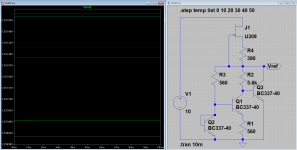
This is the shunt that I am working on.
V3 is a voltage reference like a tl431 and the voltage at the output is equal to the reference voltage.
Maybe i will open a new thread about this one.
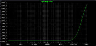
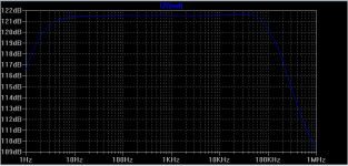
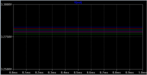
The second image is the output impedance, third is the power supply rejection ratio, the last one is the output voltage with different temperatures from 0º to 50º in 10º steps.
V3 is a voltage reference like a tl431 and the voltage at the output is equal to the reference voltage.
Maybe i will open a new thread about this one.
The second image is the output impedance, third is the power supply rejection ratio, the last one is the output voltage with different temperatures from 0º to 50º in 10º steps.
Attachments
I have design it for the es9018 analog voltage that is 3,3v , but as the components are very cheap, I will also use it in the digital voltage, the es9018 will use 3 of this.
If one wants 5 volts out the v3 will have to be a 5v voltage reference.
If one wants 5 volts out the v3 will have to be a 5v voltage reference.
This is the shunt that I am working on.
V3 is a voltage reference like a tl431 and the voltage at the output is equal to the reference voltage.
Maybe i will open a new thread about this one.
The second image is the output impedance, third is the power supply rejection ratio, the last one is the output voltage with different temperatures from 0º to 50º in 10º steps.
Looks good to me. One thing I might change, why not have a little bit of gain, then you could use a 2V (or comparable) reference and 'tune' the gain factor for 3.3 and 5 (or any other) output voltage.
Also if you use a reference lower than 3.3V then you can feed the reference from the output voltage and that may be a better option than using the 'dirty' supply.
As you may (or not) know, I do like all the BC327/337's 🙂. Makes me wonder, could one use a BC-combo as a band gap reference 🙂
A example of a positive and negative power supply , in this case +15V and -15V output.
edit: In this case the output impedance is even lower that the 3.3v exemple 300 micro ohms for the negative and 600u for the positive.
edit: In this case the output impedance is even lower that the 3.3v exemple 300 micro ohms for the negative and 600u for the positive.
Attachments
Last edited:
A example of a positive and negative power supply , in this case +15V and -15V output.
edit: In this case the output impedance is even lower that the 3.3v exemple 300 micro ohms for the negative and 600u for the positive.
At I1 = 100mA and Vout = 15V Q5 needs to dissipate 1.5Watt 🙂
A example of a positive and negative power supply , in this case +15V and -15V output.
edit: In this case the output impedance is even lower that the 3.3v exemple 300 micro ohms for the negative and 600u for the positive.
What is the ESR of C3, and is the very low output impedance a function of the ESR?
Looks good to me. One thing I might change, why not have a little bit of gain, then you could use a 2V (or comparable) reference and 'tune' the gain factor for 3.3 and 5 (or any other) output voltage.
Also if you use a reference lower than 3.3V then you can feed the reference from the output voltage and that may be a better option than using the 'dirty' supply.
As you may (or not) know, I do like all the BC327/337's 🙂. Makes me wonder, could one use a BC-combo as a band gap reference 🙂
I have think of that ,and made some sim´s, but adding gain adds unnecessary complexity, I personally use the tl431 as reference voltage , the resistor r3 and c2 filters the noise from the voltage ref.
Using a current source to feed the tl431 enhance the psrr of the voltage ref. so I do not think it will be a great gain to feed the reference from the output voltage.
I also like the BC327/337's
The things that I want to change is the main current source, and a speed up circuit for the voltage ref. filter.
At I1 = 100mA and Vout = 15V Q5 needs to dissipate 1.5Watt 🙂
Forget to say that Q3 and Q5 has to be changed to bigger ones 🙄
What is the ESR of C3, and is the very low output impedance a function of the ESR?
In this case i have sim with 3mili ohms, but the ESR just start to influence at higher frequencies when the loop gain start to fall
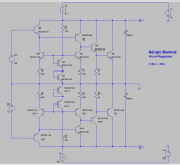
This is a similar version , but with MOSFET at the output,
The higher the Transconductance of the MOSFET the lower output impedance.
Edit: a good MOS for this is maybe IPP023N04N
:http://www.infineon.com/dgdl/IPP023...10004&fileId=db3a30431936bc4b0119522e5a143b47
The higher the Transconductance of the MOSFET the lower output impedance.
Edit: a good MOS for this is maybe IPP023N04N
:http://www.infineon.com/dgdl/IPP023...10004&fileId=db3a30431936bc4b0119522e5a143b47
Attachments

Last edited: