So why the electrolytics ?
The problem is the biasing of BJTs. JFets are self conducting and have very low gate current so DC coupling the input and making the ground reference DC coupled too is no problem. With BJts there is always the base-emitter voltage of ca. 0.65V.
In the Paradise i feed a current into the emitters and to make a ground reference i connect the elcaps from there to ground. That separates Dc and AC nicely. The music modulated signal at the emitters flows though the elcaps to ground ( only AC ) and still the DC conditions are set because no DC can flow into the elcaps ( well, a little, some micro Amperes leakage ). One advantage of the elcaps is also that they reduce hum from the power supply to the emitters. That hum is shunted to ground over a certain frequency.
So how can we DC couple ? The simplest way is to substitute the elcaps with transdiodes.
That is a BJT transistor where base and collector are connected. The transdiode is them formed from that point to the emitter. That circuit works because the transdiodes do the 0.65V level shifting and at the same time form a signal path to ground. So simply put transdiodes in the Paradise instead of the elcaps ? Well that is not that simple but doable.
Is there a disadvantage ? Yes, provided that the transdiode junction has the same noise impedance then the input stage we have a 3dB noise penalty ( hiss not hum ) and we need to run the input on double current, the transdiodes need idle too.
To avoid the 3 dB hiss penalty we can of cause shunt the transdiode with a capacitor that shunts the noise to ground. That cap can be smaller then in the Paradise, say a 1000uF Nichicon ES bipolar. Also we can insert a resistor in series with the transdiode to manipulate the current.
See such a design by our Bonsai.
Tomorrow i will show you another way that i use in the Opus Magnum.
It is a rather complex telescopic cascode. I can not publish the complete circuit because it is under NDA but i show the principle.
It has a 3dB disadvantage too but i solve that with NOS low rbb transistors. That also solves the paralleling by the way, i told you before.
Problem is to get the transistors so this is not recommended for DIY also out of other reasons. One is the parallel symmetric Gilbert 2I mirror i use.
That mirror can have an infinite output impedance but a negative infinite output impedance too. A tiny amount of miss match and the circuit goes bananas.
question: the stage you have build has no El cap to separate DC bias from AC, am I correct?
If so when you talk about Elcap are you referring to Paradise?
This circuit has coupling cap, however this can be very low value if pass resistor is increased thus gain goes up (however PSU level will have to increase with it), abd two high quality caps can be employed there avoiding extra active level shifting with folding cascode and servo circuit to control Offset.
The last question I have, is that you mention that gain is 88(dB?!), however I simulated it and for some reason I can only get 66dB (without RIAA) which would lead to about 44dB roughly and to get this value I had to increase collector resistor from 220ohm to 1K.
Is this result not mathing the real world?
Thanks.
When i talk about the electrolytics i talk about the Paradise.
The gain of the new circuit is 88 times ( x 88 ) and not 88dB.
I do not plan to make a new phono stage based on this.
The idea is to give the Paradise a balanced option because some people that use it asked about it.
So the "new" Paradise will use current mirrors and is DC coupled, also the input.
I do not need the elcaps any more in both varieties.
The question is if i finish both versions, transconductance and transimpedance or i do only one of those. Most people want to have the input impedance adjustable and that gives favour to the transconductance input.
It is harder to make a servo for this though.
I smoked a low ESR elcap, woww got that thing hot.
Both channels are working.
I decided to stop now and listen later today.
I found some issues but i tell you more tomorrow.
I decided to stop now and listen later today.
I found some issues but i tell you more tomorrow.
Here we go...
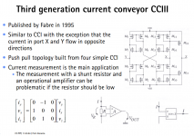
O.k. I do not know where I did get this stuff, it may even have come from here, but I thought that I should post it. Talking about 'current conveyors' did inspired me to research it and this was what I found. This circuit can take a floating source and convert it to a ground referenced voltage (yes I know there are more ways to do this, but I like it). And it is called a 'current conveyor' (rather fitting 🙂).
Attachments
You may think that I am 'dumb' but it only now comes to me that this is about the same circuit as was posted by Joachim ... mmmm ... please do not punish me 🙂
Is a capacitor a better current conveyor than two transistors. I believe that would be hard to judge without building and listening to the circuit...
Yes you are right, it needs only 2 transistors 🙂
Frans, that one you posted looks from Sansens book " Analog Essentials ".
He is a MosFet specialist but it can be converted to BJT.
It is not exactly the same then i posted. My circuit needs only 8 transistors and is AC couple. I do not know if the circuit you posted is superiour and i am not sure about the noise performance.
I like the way the matrix is written. When i studied electronics in the 70th we calculated a lot matrixes.
So why the electrolytics ?
The problem is the biasing of BJTs.
Sorry, the use of electrolytic capacitors is a wrong design decision in this circuit.
No, it is not. It is one way to to it and has advantages and disadvantages over DC coupling.
If it would be a wrong decision it would not sound as good as it does.
If it would be a wrong decision it would not sound as good as it does.
O.k. I do not know where I did get this stuff, it may even have come from here, but I thought that I should post it. Talking about 'current conveyors' did inspired me to research it and this was what I found. This circuit can take a floating source and convert it to a ground referenced voltage (yes I know there are more ways to do this, but I like it). And it is called a 'current conveyor' (rather fitting 🙂).
Found that as well and way to do current conveyor with op amps still light years away for me to turn it in to BJT.
So every single word that you or Joachim post is really welcome
Frans, that one you posted looks from Sansens book " Analog Essentials ".
He is a MosFet specialist but it can be converted to BJT.
It is not exactly the same then i posted. My circuit needs only 8 transistors and is AC couple. I do not know if the circuit you posted is superiour and i am not sure about the noise performance.
I like the way the matrix is written. When i studied electronics in the 70th we calculated a lot matrixes.
This is where I got it http://cas.ee.ic.ac.uk/people/dario/files/E416/cc_handout07.pdf
And when you Google for
https://www.google.com/search?q=sit...e7&rls=com.microsoft:en-US:IE-Address&ie=&oe=
then there is even more (mixed subjects).
https://www.google.com/search?q=sit...e7&rls=com.microsoft:en-US:IE-Address&ie=&oe=
then there is even more (mixed subjects).
Last edited:
Did you ever try OS-CONS in this place?No, it is not. It is one way to to it and has advantages and disadvantages over DC coupling.
If it would be a wrong decision it would not sound as good as it does.