OS-Cons are polymer caps. They have very high leakage current. In that position they are wrong. For power supply bypass they are an interesting option.
Theoretical they have on 1/10th of the ESR of even very low ERS conventionalelcaps.
Theoretical they have on 1/10th of the ESR of even very low ERS conventionalelcaps.
OS-Cons are polymer caps. They have very high leakage current. In that position they are wrong. For power supply bypass they are an interesting option.
Theoretical they have only 1/10th of the ESR of even very low ERS conventional elcaps.
Read the fu... manual.
Theoretical they have only 1/10th of the ESR of even very low ERS conventional elcaps.
Read the fu... manual.
I like the way the matrix is written.
Always nice if it's singular

We went up to nine dimensions. No pocket calculator allowed.
When i go through my old material i do not understand anything.
Was that me that solved this equations ?
Obviously.
When i go through my old material i do not understand anything.
Was that me that solved this equations ?
Obviously.
The circuit from post 8551 is working.
I did not know if it would play floating at the input so on one channel i put 2kOhm resistors from each input to ground. I found that this is not necessary. The only thing that happened was that the ground referenced input had a bit less gain so i took out the resistors and listened floating.
Wow, this stage is quiet ! Hum and hiss of my power amp is higher then this circuit cranked up.
The sound is different from the balanced transconductance version.
Bass is stronger and more slamming. I even had to readjust my subwoofers.
Dynamics and resolution are quite dramatic. 3 dimensional space is big and well focussed.
The only thing that some may not like is that it is not as smooth as the transconductance version. You can interpret this as a lack of energy in the transconductance or a more rough and ready sound in the transimpedance. The circuit is not run in so that may change.
I am now trying to implement this input stage into the Pardadise.
I have some PCBs to try that out.
Maybe i can persuade MiiB to help me to get this going. Of cause the servo has to be changed too.
I found two caveats that i talked about earlier.
One is that this circuit has an overshot on the square wave. I think that comes from the mirror chosen. You can see such behavior in Frans links and it can be solved by changing the mirror slightly. It is not a big problem anyway because the resonance is so high up that no information is on the record any more. Of cause ticks and pops can have a very extended range so i will try to get the resonance away.
The other issue surprised me :
There is about 0,3mV off offset between the inputs although both inputs should be on the same DC level.
Why that is i have already discussed with AS Audio.
It can be that it is because i did not select the transistors, not Hfe and not Ube. I just took what i found in my storage as a worse case experiment. It could be ether this or we find an offset trim.
Attachments
The circuit from post 8551 is working.
I did not know if it would play floating at the input so on one channel i put 2kOhm resistors from each input to ground. I found that this is not necessary. The only thing that happened was that the ground referenced input had a bit less gain so i took out the resistors and listened floating.
Wow, this stage is quiet ! Hum and hiss of my power amp is higher then this circuit cranked up.
The sound is different from the balanced transconductance version.
Bass is stronger and more slamming. I even had to readjust my subwoofers.
Dynamics and resolution are quite dramatic. 3 dimensional space is big and well focussed.
The only thing that some may not like is that it is not as smooth as the transconductance version. You can interpret this as a lack of energy in the transconductance or a more rough and ready sound in the transimpedance. The circuit is not run in so that may change.
I am now trying to implement this input stage into the Pardadise.
I have some PCBs to try that out.
Maybe i can persuade MiiB to help me to get this going. Of cause the servo has to be changed too.
I found two caveats that i talked about earlier.
One is that this circuit has an overshot on the square wave. I think that comes from the mirror chosen. You can see such behavior in Frans links and it can be solved by changing the mirror slightly. It is not a big problem anyway because the resonance is so high up that no information is on the record any more. Of cause ticks and pops can have a very extended range so i will try to get the resonance away.
The other issue surprised me :
There is about 0,3mV off offset between the inputs although both inputs should be on the same DC level.
Why that is i have already discussed with AS Audio.
It can be that it is because i did not select the transistors, not Hfe and not Ube. I just took what i found in my storage as a worse case experiment. It could be ether this or we find an offset trim.
I have already integrated this input stage into the paradise and designed servo which us simply non inverting instead of inverting.
The folded cascaded stays as is and the bias for input stage comes from current mirror just like paradise.
I will postage circuit later. I do really like this topology the absence of bias capacitors and dc coupled.
However I still haven't ran noise anysis I will do later.
Stupid question: why would a balance input stage se output be better than transZ se in se out?
Would it be worth to try to convert this balanced all the way through?
I will try to breadboard the circuit tonight and see what happens.
AS, yes, i am using the BC140-160. This BJTs must be at least 40 years old. They do great on the curve tracer and i knew from the " old times" that they are low noise.
I did not expect that the are this good. Maybe the process to make them has changed over the years for the better. I am using new ones from Continental Semi.
It has to be seen if vintage one do as well. You never know what chip is in the package.
Stefanoo, please publish the circuit and thanks that you are tying it as input of the Paradise.
I think balanced ( transimpedance or not ) has advantages at the input in terms of low level resolution. External hum is supressed well and the balanced supresses second harmonic. To make the complete RIAA balanced whould require that each channel has two RIAAs. These have to be matched to better then 0.1% for a meager 40dB common mode supression. Also small diffenced in the two chains can lead to cancelation of certain areas of the frequecy response. On the other hand i build commercial RIAAs that are balanced from in to out. One is called " Rauschfrei" and retails for 6800,- €, just to give you an idea in what class i put it. I think it sounds pretty well so by selecting the RIAA components it can be done. My most expensive stage, the Primal Scream ( even more expensive then the Opus Magnum ) is also balanced in - balanced out with double RIAA. Here i trim the caps with teflon trimmers.
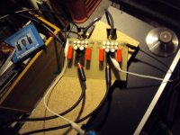
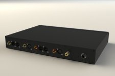
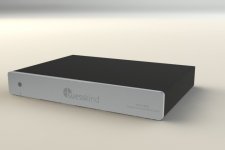
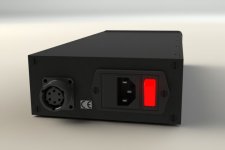
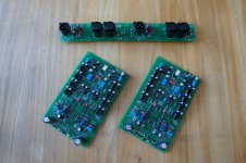
Here are some pictures of the Rauschfrei.
When you look at the mainboard you see that it is balanced from in to out.
Unbalanced from in to out is switchable so i was able to compare.
By the way the Rauschfrei has a parallel symmetric-balanced JFet input and is DC coupled from in to out.
When you look at the mainboard you see that it is balanced from in to out.
Unbalanced from in to out is switchable so i was able to compare.
By the way the Rauschfrei has a parallel symmetric-balanced JFet input and is DC coupled from in to out.
Attachments
I see BC140 / 160 type 16 Hfe160 at 100 mA is this correct?
Pants about the 0.3mV at the imputs😀
Did you mesure this whith MC loading resistor?
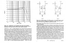
I see graph goes up to 10 G
Pants about the 0.3mV at the imputs😀
Did you mesure this whith MC loading resistor?
I see graph goes up to 10 G
Last edited:
Yes, they have around 160 Hfe, also at the 10mA i run them on.
For the standard Paradise they do not work so well because input impedance will go down quite a bit and the Paradise structure works better with high Hfe because the input stage has also current gain. In common base, like the circuit i just build, this is not a problem.
A common base stage makes an I/U conversion and has no current gain, only voltage gain.
At your discrettion Wuld it be possible to intgrate this on the Paradise?
I am going to start populating the R3 boards and maybe it is feasible to integrate this on a doughter board.
I am going to start populating the R3 boards and maybe it is feasible to integrate this on a doughter board.
That is what i try. Make a balanced-transimpedance input for the Paradise.
I am thinking to use the Paradise as motherboard with the new ( alternative ) input stage stacked on top as a " child".
I am thinking to use the Paradise as motherboard with the new ( alternative ) input stage stacked on top as a " child".
Briliant I am looking forward to a back to back listening session with the Paradise R2 even better if some one near by wants to join in...
PS I am in Chester UK
PS I am in Chester UK
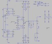
Joachim,
here is the paradise with the transconductance input stage.
It simulates ok.
I would rather have simpler resistors instead of the extra complexity of current mirrors controlled by the servo, but then I don't know how to arrange a working servo unless servo goes on the output stage.
However by doing that, the input stage might drift too much which I don't like as good practice.
Let me know if I can help further with this.
Also I think at this point it would be good to go balance all the way through.
Matching capacitors for DYIers should not be a problem.
I think problem arises when manufacturer try to produce a product with double RIAA.
Since we are not manufacturing I think we can do it 🙂🙂😎
Attachments
Thanks Stefanoo. That looks like it works. You use emitter resistors, i asume to lower distortion and input offset.
I think we can do two things :
One is to implement this input stage into the Paradise, what you have done.
I think a lot of people whould apreciate this option.
This could be then done as a small aditional board. As far as i can see a lot of the existing Paradise can be used.
The other is to make a fully balanced stage. For that we would need a totally new layout. Maybe we can put that version into the Masterpiece thread.
The problem is that it is not that easy to follow this new input stage with a balanced transimpedance RIAA. What i would do instead is make a shunt feedback RIAA with the OPA1632. This is a fully balanced chip. It is used by Rowland and also by Mark Levinson in their most expensive stuff. I do not like to open a discussion if that equipment sounds good. I can only tell you that this chip sounds excellent and is very hard to beat with a discrete design.
Last edited:
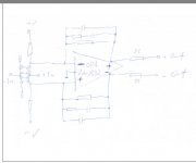
I am not 100% sure about the input arangement but this is the priciple.
The OPA1632 has a reference pin that i have connected to ground.
It can also be put on a servo so we could maybe not need the bias servo at the input.
That servo has to be diffential because both output have to be held on zero DC but also the voltage from one output to the other.
The OPA1632 has a reference pin that i have connected to ground.
It can also be put on a servo so we could maybe not need the bias servo at the input.
That servo has to be diffential because both output have to be held on zero DC but also the voltage from one output to the other.