It is a bit a matter of philosophy if the input needs emitter resistors or not.
Distortion goes down but also gain.
The cartridge itself could be looked at as emitter degeneration.
I will first build it without. I find the noise reduction attractive.
Distortion goes down but also gain.
The cartridge itself could be looked at as emitter degeneration.
I will first build it without. I find the noise reduction attractive.
Sure, the following stages can be like the Paradise.
That gives the option to implement it in the Paradise if someone wants a balanced transimpedance input.
Of cause the balanced transconductance input i already build can also be implanted in the Paradise.
That gives the option to implement it in the Paradise if someone wants a balanced transimpedance input.
Of cause the balanced transconductance input i already build can also be implanted in the Paradise.
I think it is a good idea to make a balanced option for the Paradise.
I had a busy day. Nevertheless i have one balanced transimpedance input nearly ready.
I build the simpler version i posted before. The helpers and CCSs can be added later.
I will listen if that brings any audible benefit.
I had a busy day. Nevertheless i have one balanced transimpedance input nearly ready.
I build the simpler version i posted before. The helpers and CCSs can be added later.
I will listen if that brings any audible benefit.
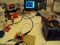
One channel is working !
Gain is quite high now. I use a " cartridge dummy " of 5 Ohm so gain is about
220 x 2 / 5 = 88.
Under that conditions the frequency response goes to a little under 2 Mhz - 3dB.
See the picture. Gain-Bandwidth according to this is around 100MHz, more or less the transit frequency of the used transistors. This circuit does not have Miller multiplication.
It is fast. How i measure a balanced transimpedance input with a single ended generator of 50 Ohm output impedance is my secret. Non of the German magazines and their associated labs can do it so when a transimpedance RIAA is tested you do not see any measurements. Ask the guru.
Attachments
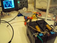
As i suspected the circuit can be run on a floating supply. You see in the right picture that the center tab between the batteries is disconnected.
What is the advantage of floating ?
That would deserve a separate thread.
What is the advantage of floating ?
That would deserve a separate thread.
As i suspected the circuit can be run on a floating supply. You see in the right picture that the center tab between the batteries is disconnected.
What is the advantage of floating ?
That would deserve a separate thread.
Floating center tap might promote further isolation.
Good for low current preamps working in class A ?
Not very good if one of the rails pulls more current than the other https://mail-attachment.googleuserc...878&sads=DdfLofjqvCU2hzi5Y7x7spId_m4&sadssc=1
What flows in flows out. That is Kirchhoff.
When it is done right it should reduce distortion ( in an open loop circuit ) to the parasitics.
The parasitics are most of the time un linear input and output capacitances.
Also think about ground contamination.
When it is done right it should reduce distortion ( in an open loop circuit ) to the parasitics.
The parasitics are most of the time un linear input and output capacitances.
Also think about ground contamination.
Big trannies.. BC 140 160.... How is the noise...?? Nice with the high gain, makes a Oneshot Riaa possible.🙂
How i measure a balanced transimpedance input with a single ended generator of 50 Ohm output impedance is my secret. Non of the German magazines and their associated labs can do it so when a transimpedance RIAA is tested you do not see any measurements. Ask the guru.
Using a pseudo balanced attenuator with 5 Ohm shunt legs?
Yes Salas, it is simply 2 100 Ohm resistors, one in each feed ( ground and hot ) and a 5 Ohm across. The output at the left and right side of the 5 Ohm resistor then goes into the phono stage.
That is a good approximation of a 5 Ohm floating source.
That is a good approximation of a 5 Ohm floating source.
MiiB, so far i have tested the BC140-160 in the balanced transconductance stage and noise was low.
I am really surprised how many BJTs are out there that have low voltage noise. The problem is to find them because most spec sheets tell us nothing about low noise at low impedances.
I am really surprised how many BJTs are out there that have low voltage noise. The problem is to find them because most spec sheets tell us nothing about low noise at low impedances.
Today i will build the second channel and then listen
It is very easy to build because it is mostly made up from transistors.
It is very easy to build because it is mostly made up from transistors.
Yes Salas, it is simply 2 100 Ohm resistors, one in each feed ( ground and hot ) and a 5 Ohm across. The output at the left and right side of the 5 Ohm resistor then goes into the phono stage.
That is a good approximation of a 5 Ohm floating source.
😉
When you look back on this thread i already did a lot of work on transimpedance inputs.
What bugged me is the input offset. I think this is solved when the input is balanced.
The other was how to measure such an input. After some brain storming i got the idea of the floating resistive divider and it worked.
It has also the advantage that the generator can be run on a comfortable voltage range and the devider also reduces noise from the generator.
I had that idea from Dough Self when he measured at low volume but his implementation was single ended.
The Dan Rather Approved Douglas Self Site
Look at Fig.2
Very good text... thank you Joachim
Please excuse my offroad humour somewhere else 🙂
The second balanced transimpedance input is nearly ready. I will measure it and put it in the system. It is late here so i can only listen at low volume. Without music i can crank it so i will find out if there is any hum or hiss.
What is next ? Well, we had that discussion about the input stage of the Paradise.
2 things have being critizized : transistors in parallel, electrolytics in the emitter feed.
It was said that parralel transistors give a less focussed sound, as far as i remember in the bass. I do not second this at all. First the input transistors get selected, second they have quite high emitter resistors so currents should be very well balanced. There are thermal issues but that can be solved by putting the input transistors on the same heat sink or putting them in a box. A simple cartbord box is sufficient.
The only way to avoid paralleling is to use very low rbb transistors and run them on high current. Problem is that it is nearly imposible to get the special ROHM, Toshiba or Hitachis. ROHMs are long extict, then came the Toshibas and now i can not even get the Hitachis like a halve year ago. I am searching for alternatives and found some. Problem is that most of them do not have high Hfe and that would increase the input offset in the Paradise. OK, there is the offset trim on the R3 but input impedance will be reduced in proportion to the Hfe loss. As i said, i have no problem with paralleling and it can be solved by using super low Rbb transistors. So the 4 pairs of BC327-337 can simply be substituted with one pair of super low rbb ones run on 10mA ( that is the total of the 4 pairs, 4 x 2.5mA ). The emiteer resistors have then to be 33/4 = 8.25 Ohm. They can be even lowered to 3.3 - 5 Ohm. That gives more gain and less current feedback.
That thing with the electrolytics. Why are they there ?
How can we DC couple that part ? More tomorrow.