The IF3901 is like a pink elephant or a unicorn if you wish.
Can not wait until you get some Stefano.
The CSS has to provide THE EXACT SAME CURRENT THEN THE INPUT STAGE PROVIDES AT IDDLE, ALL THE TIME. If that does not happen the DC voltage at the output node is not EXACTLY at 1/2 voltage of the supply. That condition gives the MAXIMUM DYNAMIC RANGE ( Tietze- Schenk ).
I am also thinking that with one monolithic i.e. one pair of IF there should be plenty of gain, very low noise more thermal stability due to the monolotic.
I was also thinking why wouldn't we use Jfet for the current source?
In this instance using the same paralled IF monolithic?
Is it a stupid idea?
I thought that making the CSS also a J-Fet BJT cascode could give it a similar drift so that the drift cancels. Problem is that this will cut the output impedance in half. We loose 6dB of gain that way. We could of cause then make the RIAA resistive components two time higher to restore the gain. If that is a good idea i can not say.
Of cause we could make the top J-Fet BJT cascode higher in impedance but that may introduce drift gain.
Sorry, i did not find the time to find my old solution. I think it was a decoupled LM317 CCS on top of a BJT cascode. It was parallel symmetric though so some of the drift cancels.
That is then a kind of Paradise without the mirrors. So you understand part of the history why the Paradise saw the light of day.
That is then a kind of Paradise without the mirrors. So you understand part of the history why the Paradise saw the light of day.
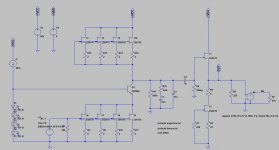
here is the idea I was describing before.
It onlu gives 46dB gain which is clearly not enough.
The problem however is:
1) the noise simulation shows 0.87nV/rtHz for only 46dB which puts it into the noisy side
2) the topology is INVERTING and I don't think there is much it can be done here. I would have expected that since output is sourced from a common source
Another thing that needs to be noted and that I just thought of is that output of the first stage can't be half of the rail, this wouldn't lead to maximum headroom, but has to be rail-Vcascade-2V(for saturation) which clearly shows that for good headroom capability you need high voltage rail which migh be a problem for regular JFets or at least operating to their maximum derating.
Attachments
You can put a BJT as cascode on top of the j-Fet current source.
Phase inversion is no problem. Revers the cartridge leads, they are not balanced but floating.
Phase inversion is no problem. Revers the cartridge leads, they are not balanced but floating.
Last edited:
When you use BF862 instead of 2SK170 the gain goes up and the noise goes down.
One way to raise the gain is of cause to double the values of the RIAA resistors and half the values of the caps. You can still use your teflons, just put them in series.
One way to raise the gain is of cause to double the values of the RIAA resistors and half the values of the caps. You can still use your teflons, just put them in series.
Yes, when i talked about best dynamic range at 1/2 supply voltage i forgot the saturation headroom. Good catch.
If you do not have BF862 models simply use 8 x 2SK170. That of cause raises the input capacitance and that can create an oscillator at very high frequencies. That can be avoided with 0.1uH coils in each gate.
Frans, a PM send.
You get an older bottle anyway.
Joachim, you make me look like some kind of an expert 🙂 thanks.
I really do not know, but if I was guessing I would go like this, the larger the mosfet the better 🙂 in actual fact a large (hexfet) mosfet is a matrix of paralleled fets and thus the more in parallel the better. Thus I think the larger the dye the better. Just my guestimate! You know where to send that bottle 🙂
Some research and I found:
The current path is created by inverting the p-layer underneath the gate by the identical method in
the lateral MOSFETs. Source current flows underneath this gate area and then vertically through
the drain, spreading out as it flows down. A typical MOSFET consists of many thousands of N+
sources conducting in parallel. This vertical geometry makes possible lower on-state resistances
(RDS(on)) for the same blocking voltage and faster switching than the lateral MOSFETs.
In http://www12.fairchildsemi.com/an/AN/AN-558.pdf
The number of parallell fets is 'many thousands' 🙂
Last edited:
this last post definitely sealed the deal!!! No more comments? No more progresses on the last circuit?
😱😱😱
😱😱😱
For two days we have hard snow here.... My vehicle decided to stall... I have been updating my automotive knowledge... after verifying the fuel pump does produce enough pressure to the rail, I got a clue from a friend and focused myself in the electric circuit.... finally found the issue... bad ignition coil... Today, another highly stressed morning... had to climb a hill to borrow a car from another friend... transport kid and wife to the plain, go shop for a coil, get back, replace the coil... car starts... loose fixing nuts... go to garage, borrow magnetic tool, find nuts... fix everything... One of my students gave up classes.... today is payday... lots of €€ transfers... barely enough... so no time for pushing you guys 🙂
I am sorry to hear that but we live in a high snow - cold weather area too.
I certainly know that kind of problems. Anyway, life goes on.
I certainly know that kind of problems. Anyway, life goes on.
I allready learned how to enjoy each moment in life.... so even climbing the hill under heavy snow seemed like revigorating to me 🙂
that's the good spirit Ricardo!!!! 🙂
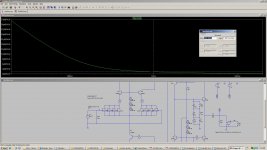
Now to comment on some progresses I made on the design, do you guys still remember the one shot approach?
I modeled it up as it seems to be a pretty nice circuit.
it can be easily obtained 62dB out of it, non-inverting topology.
However Noise simulation would seem to rule this out. Below is the noise simulation's result.
Residual noise would be comparable to a modified paradise without ElCap which sounds wonderful, but IMHO noise is unacceptable.
Some reasonable noise level could be 0.7nV/rtHz.
Any comment? Is it possible to fix this?