Hi Frans,
I guess I(R3) should read I(R5)?
A51 might be a cap multiplier, but then, I would think it should work way better. And not without first cap...
Rüdiger
I guess I(R3) should read I(R5)?
A51 might be a cap multiplier, but then, I would think it should work way better. And not without first cap...
Rüdiger
I would not use a chopper Opamp for servo.
Frans, so far i have no idea. Does the circuit have any voltage drop ?
Yes is has (like any circuit) but this a bit more 🙂 The question though is: Is this the kind of result the other circuits (stepped rectifier and charge transfer) are aiming for (and they are dropping volts).
Hi Frans,
I guess I(R3) should read I(R5)?
A51 might be a cap multiplier, but then, I would think it should work way better. And not without first cap...
Rüdiger
There are no caps in the 'Area 51' circuit. If there would be caps, then the peak currents from the transformer, and into the rectifiers, would be larger.
Is there any semiconductor in series with the power line in the area 51 ?
Yes there is 🙂 it is an 'non human' (actualy 3 legged) [not like us (2 legged)] device 🙂
I found 0.4W 0.1% 15ppm Precision metal film resistors from Vishay MBB series on rapidonline. It seems these are similar to welwyn RC55. Are these MBB suitable for this project ?
Yes there is 🙂 it is an 'non human' (actualy 3 legged) [not like us (2 legged)] device 🙂
So another part there.... should be audible.
Is it this ones :http://www.rapidonline.com/pdf/63-1000e.pdf
They are made by Beyschlag. Should be good. I would use higher wattage though or you could more or less use any good quality film resistor.
They are made by Beyschlag. Should be good. I would use higher wattage though or you could more or less use any good quality film resistor.
Measuring distortion in resistors is not easy and there is disagreement between the experts. Bateman does think that a higher wattage resistor does not automatically measures better and he also thinks that magnetism is no concern.
Ed Simon thinks otherwise.
http://www.linearaudio.net/userfiles/file/letters/Volume_1_LTE_ES.pdf The Welvyn RC55 is magnetic for example. Still it is a good sounding and measuring resistor.
Maybe we should all gather in some month and compare our versions.
Ed Simon thinks otherwise.
http://www.linearaudio.net/userfiles/file/letters/Volume_1_LTE_ES.pdf The Welvyn RC55 is magnetic for example. Still it is a good sounding and measuring resistor.
Maybe we should all gather in some month and compare our versions.
I have been using the RC55 for quite same time.
The MBB0207 series does look realy good on paper and at a third of the priece I pay for the Welvyn I will certanly give that a try.
Another big pluss the values they have in stock go down to 10R
I cound only get the RC55 from 33R upwards
Tanks for top tip
The MBB0207 series does look realy good on paper and at a third of the priece I pay for the Welvyn I will certanly give that a try.
Another big pluss the values they have in stock go down to 10R
I cound only get the RC55 from 33R upwards
Tanks for top tip
The Dale MilSpec stuff is good enough for me.
I think the RC60 is in fact non-magnetic. There have been non-magnetic variants of RC50-55 around as well, but I think these need to be a special order.
I think the RC60 is in fact non-magnetic. There have been non-magnetic variants of RC50-55 around as well, but I think these need to be a special order.
... so much happening over the weekend....
interesting discussions as usual! too bad the party happened without me...
here some comments on the snubber and rectifier thing:
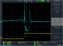
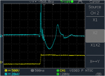
A faster diode (UF400x versus 1N400x) will create less noise energy but the noise spectrum will be higher in frequency. This makes it easier to filter, provided shielding is good enough. Check out the attached pictures ("slow" and "fast"), this application was a swithc-mode power supply but the pictures illustrate the moment when the current in the diode changes. The blue line has been taken wiht a magnetic field sensor (see bcarsten.com how to build your own). Slow diode has a lot more energy in the areas above and below the curve, as compared to the fast one....
The reverse recovery (and in some cases not relevant here, the forward recovery) of a diode causes a current spike that can make resonant circuits in its surrounding ring, and the snubber needs to be designed to reduce the side effects. So the cap will allow you to set the frequency (within limits), and the resistor is needed to dampen the amplitude (q factor of this resonant circuit). The values will depend on the diodes and other circuit elements used (pcb etc), so its hard to give a formula. There may also be component variations.... with a fast diode, best to try e.g. 10 ohms and 10nF and then check the magnetic field, so you get a fast decay without the nasty spikes.
SiC (and GaN) diodes, as well as tube rectifiers, have hardly any (or even no) reverse recovery charge, removing a big portion of that problem straight away. Only problem is the price (SiC) or size (Tubes)
The lower-impedance the input rectifiers are, and the larger the capacitors, the higher the current spikes will be. If the load current is (comparatively) small, the "conduction angle" (the % of time the input rectifiers are actually conducting) gets smaller and smaller. This is good and bad - the shorter it is, the longer is the time the power supply is actually isolated from input noise. At the same time the current spike is of course higher so that needs to be taken care of.
Tube rectifiers have the max current specified in the datasheet. Their impedance is rather high, so the charging goes very slow. Low current spike, but noise from the grid has a long time to come in.....
My guess for Area51: a choke.....
just my two cents....
interesting discussions as usual! too bad the party happened without me...
here some comments on the snubber and rectifier thing:
A faster diode (UF400x versus 1N400x) will create less noise energy but the noise spectrum will be higher in frequency. This makes it easier to filter, provided shielding is good enough. Check out the attached pictures ("slow" and "fast"), this application was a swithc-mode power supply but the pictures illustrate the moment when the current in the diode changes. The blue line has been taken wiht a magnetic field sensor (see bcarsten.com how to build your own). Slow diode has a lot more energy in the areas above and below the curve, as compared to the fast one....
The reverse recovery (and in some cases not relevant here, the forward recovery) of a diode causes a current spike that can make resonant circuits in its surrounding ring, and the snubber needs to be designed to reduce the side effects. So the cap will allow you to set the frequency (within limits), and the resistor is needed to dampen the amplitude (q factor of this resonant circuit). The values will depend on the diodes and other circuit elements used (pcb etc), so its hard to give a formula. There may also be component variations.... with a fast diode, best to try e.g. 10 ohms and 10nF and then check the magnetic field, so you get a fast decay without the nasty spikes.
SiC (and GaN) diodes, as well as tube rectifiers, have hardly any (or even no) reverse recovery charge, removing a big portion of that problem straight away. Only problem is the price (SiC) or size (Tubes)
The lower-impedance the input rectifiers are, and the larger the capacitors, the higher the current spikes will be. If the load current is (comparatively) small, the "conduction angle" (the % of time the input rectifiers are actually conducting) gets smaller and smaller. This is good and bad - the shorter it is, the longer is the time the power supply is actually isolated from input noise. At the same time the current spike is of course higher so that needs to be taken care of.
Tube rectifiers have the max current specified in the datasheet. Their impedance is rather high, so the charging goes very slow. Low current spike, but noise from the grid has a long time to come in.....
My guess for Area51: a choke.....
just my two cents....
Attachments
Last edited:
When i want to use a better quality resistor i use Dale too. I buy them from Mouser.
Some are magnetic, some not. When you want to be sure that they are non magnetic buy at Schuro. They sell only the RC55 and they are rather expensive.
Thanks Hesener, this is interesting. Is it this one ? - Hfield
Actually i have build my own sniffer probe, but for detecting noise in turntables. It is actually a phono circuit with a coil at the input. Placing that coil near the motor i can even hear un perfections in the belt when it moves across the pulley and also the reaction of the motor. When a blemish in the belt moves over the pulley the motor makes a strange noise. As pickup coil i use an air core inductor of rather big size.
The Columbia replay characteristic and more
Hi guys,
Got some fascinating article from gary Galo on the Columbia replay characteristic and related stuff.
Quite interesting to read that what we take for granted (a standard RIAA curve) was all over the place in the young days of record replay.
I put it on line here; should be good reading in a quiet moment 😉
jan
Thanks Jan. It is fascinating to watch you going into vinyl research. I warn you, it is addictive and takes away a lot of brain power you could use for something more profitable...... 🙂
Thanks Hesener, this is interesting. Is it this one ? - Hfield
Actually i have build my own sniffer probe, but for detecting noise in turntables. It is actually a phono circuit with a coil at the input. Placing that coil near the motor i can even hear un perfections in the belt when it moves across the pulley and also the reaction of the motor. When a blemish in the belt moves over the pulley the motor makes a strange noise. As pickup coil i use an air core inductor of rather big size.
Yes, thats the one. We use it to detect magnetic hotspots in power supplies. The inductance of 10turns is very low, so it only works well at highish frequencies, but if you increase to 100 turns or so it should be fine. Or put a little piece of ferrite in there....
Depending on the strength of the field, you don't even need a preamplifier, most scopes can detect the signals fine (at least from power supplies - the more subtle stuff happening 70dB down of course not...)
Thanks Jan. It is fascinating to watch you going into vinyl research. I warn you, it is addictive and takes away a lot of brain power you could use for something more profitable...... 🙂
It's all your fault Joachim, you're the one that infected me 😀
jan
Many thanks Hesener for this idea. I am now really looking forward to build the Paradise.
I already build the pre-regulator, with silicon carbide bridges.
I already build the pre-regulator, with silicon carbide bridges.