Yes, the current draw is that way. The specs look good. Usually i do not make what people tell me. I was a difficult child. Too many quesions, too few answers. Actually i was cool with my grandparents. Such wonderfull and resourcefull peaple.
Actually they have around 16.2 Ohm and one side has a llittle tolerance. I will measure in 5 minuts. The Fets are quite warm but not hot after 15 min. I think 0.1V difference will not mess up my stage.
Actually they have around 16.2 Ohm and one side has a llittle tolerance. I will measure in 5 minuts. The Fets are quite warm but not hot after 15 min. I think 0.1V difference will not mess up my stage.
Its entirely up to the Vf of the Leds you used for Vrefs (5in row). If you want to match exactly it will be a drag now to select again, they are soldered.
1.678 minus and 1.601 plus.
103 & 98 mA per rail. You need 50mA per rail, cool split setting. Were those leds 1.7Vf spec?
The guy that sold me the boards at the Frickelfest for a rediculous low price gave me all the Led´s and Pannasonic 100uF caps for free so i do not know. Voltage got a little down now after time, maybe 0.1V. The Fets near to the input get a bit warmer then the ones at the ouput. I dicided to use my experimental stage instead of Martinas. It´s easier to modify and i do not destroy my long hours of work. The current draw it that stage is very similiar and i can work with shorter cabling. I have it ready in half an hour.
With green it normally hits more Vout and more 3Vf-Vgs/Rset. I know from the very many reports in the full DCB1 thread. Look like 1.7V reds to me. More secure for noise. All well then. Successful start.🙂
i have connected the phonostage and something is wrong. The voltage maesures 5.5V positive and 8.5V negative. The 5 Leds do not ignite on the positive channel. Maybe this stgae draws less then i thought or what is wrong ?
Yes measure. If the project it draws too low then the shunt Mosfets must feel too hot anyway. Else something in the load puts it in to oscillation. Are there additional stuff on the rails of that load?
If they shunt the output cap's ESR to near zero its oscillation. See about what the draw is first, then see it still works on dummy, if yes, plus nothing burned, try without the local little caps.
I measure slightly over 1V in both the negative and positive line over a 10 Ohm resistor so my estimate is spot on. I will insert the dummis then test and then take the shunt caps out.
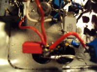
Here you see the shunt caps and how the Hypnotize is connected to the Phonostage.
Here you see the shunt caps and how the Hypnotize is connected to the Phonostage.
Attachments
So first thing is you mainly starved it. Thats 100mA draw per rail. The neg leds are dim since there is a something little left bcs that side was doing 103.5mA. Cut slack above consumption needs. You can use yet another 33R for instance if what you need now is really 100mA per rail and nothing else goes on.
What is that stage? Hulk phono?😀
What is that stage? Hulk phono?😀
i inserted the dummies, everything ok. i cut of the caps, no success. i put a scope on the lines. my resolution at home is only 5nsec and all i could see is a more or less straight line with some 2mV of indistinguished ripple. i measured AC over the lines with a very fast true RMS meter. 1.7mV on both channels. my meter can resolve frequencies to 1 MHz but the frequency counter shows nothing. when there is oszilation it must be over 40MHz. the phonostgae is one of my experimental stagess i can unfortunately not show here on this thread because it is nondisclosure work. many of my partners got very neurotic when they look at this thread. i have given away a lot of things that you normally do not see on a DIY forum but here i am crossing a fine line.
the general trend of my work at the moment is to increase bandwidth and gain and lower open loop distortion. the noise problem i have solved and at 0.28nV/qHz we hit a brickwall at room temperature. even cooling down -80° did not help much as SYN08 was reporting where he now is. that effect sets in at much lower temperature and we are talking about -200° celsius here. if then that hypothetical amplifier has any good maners in the audible range is not known to me. with the Lundal i recommended it is easyly solved. in 1:20 connection it has the Johnson noise of a 1 Ohm resistor eg. 0.1nV/qHz and then we run into problems with contacts, solder and wiring. fortunately the Lundahl is very extended in the treble and i can hear no loss whatsoever even on my very extended horm ribbons.
the general trend of my work at the moment is to increase bandwidth and gain and lower open loop distortion. the noise problem i have solved and at 0.28nV/qHz we hit a brickwall at room temperature. even cooling down -80° did not help much as SYN08 was reporting where he now is. that effect sets in at much lower temperature and we are talking about -200° celsius here. if then that hypothetical amplifier has any good maners in the audible range is not known to me. with the Lundal i recommended it is easyly solved. in 1:20 connection it has the Johnson noise of a 1 Ohm resistor eg. 0.1nV/qHz and then we run into problems with contacts, solder and wiring. fortunately the Lundahl is very extended in the treble and i can hear no loss whatsoever even on my very extended horm ribbons.