In sim the 100nF lead to a ~0.2dB loss above 1kHz.
Circuit in 9883?
JG told me this is 100pF - I even read 100uF..
in sim the ZVP3306A/ZVN3306A work alot better than the bipolars, and also work better than the BSH/BSS.
Yes I know 🙂
take a look at the Gate compensation networks.
Seems the caps could be reduced in value.
Yes 🙂
ps. We are the champions ....
Naturally 🙂
.... and tonight we´ll become soccer Champions
Who cares 🙂
Yes, C1 makes an AC short between the cascode outputs.
C1 or not to C1 that's the question 🙂
Makes a less then 1dB difference. 🙁
Hi,
In sim the 100nF lead to a ~0.2dB loss above 1kHz.
😀
I see that in a sim too.
Maybe the MosFets need no compensation at all.
i try that tomorrow.
Now i go to public viewing.
i try that tomorrow.
Now i go to public viewing.
Circuit in 9883?I see that in a sim too.
JG told me this is 100pF - I even read 100uF..
Now i go to public viewing.
P.V. means Leichenschau. Denglisch ist doch schwer ..
Hi,
Besides the bias-mod, take a look at the Gate compensation networks.
IMO there is no compensation needed (on the mosfet) probably the gate stopper will not be needed (also).
It is the impuls response of a bandpass filter :http://www.polyvalens.com/blog/wavelets/theory/
Stange enough that gives the amplitude pluse the location ( phase ).
doing an FFT gives us say the distortion products, K2, K3 .... but it does not give us the time when they appear.
i made a special Keantoken feed forward buffer that was able to compensate the distortion in my Quant Asylum Analyser to near zero by feeding in residual distortion of the oposite phase.
distortion cancelation is very different from negative feedback but who cares ?
It is the impuls response of a bandpass filter :http://www.polyvalens.com/blog/wavelets/theory/
Strange enough that gives the amplitude plus the location ( phase ).
Doing an FFT gives us say the distortion products, K2, K3 .... but it does not give us the time when they appear.
I made a special Keantoken feed forward buffer that was able to compensate the distortion in my Quant Asylum Analyser to near zero by feeding in residual distortion of the oposite phase.
Distortion cancelation is very different from negative feedback but who cares ?
It opens up a new door but who walks in ?
Last edited:
Wavelets are used as compression algorithms like JPEG and MP3.
It could also be used for decompression and together with spile algorithms for hidden data retreavel. That could breath new air in digital reproduction like CD or DSD.
It could even be used to decompresss a CD version of a master tape when the content of the master tape is known. Angels on the tip of a needle.
Everything is in everything.
Calvin, i think you made a wrong calculation with the emitter resistors.
I changed now the 25 Ohm at the input to 120 Ohm and the 25 ohm at the output into 4 Ohm. I get now 35mA idle.
As far as i understand the voltage over those emitter resistors is the same.
The input idle remained because of the CCS but the voltage that develops over the 120 Ohm resistor is higher then before, around 0.145V.
0.145V over 4 Ohm is 36mA.
When i change back to 25 Ohm at the output we have 0.145 / 25 = 5.8mA that is more plausible.
I also do not think that the combination of 120 Ohm and 3.3 Ohjm ( in my sample 4 Ohm ) is the sweetspot of that circuit.
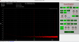
You will see in the measurements i made that the original starved version has lower THD.
The version with 35mA has a little bit lower K3 which is good but K2 went up by 10dB.
For the sound that may be even good but i will try to reduce the idle in the output to 6mA and see what happens,
I changed now the 25 Ohm at the input to 120 Ohm and the 25 ohm at the output into 4 Ohm. I get now 35mA idle.
As far as i understand the voltage over those emitter resistors is the same.
The input idle remained because of the CCS but the voltage that develops over the 120 Ohm resistor is higher then before, around 0.145V.
0.145V over 4 Ohm is 36mA.
When i change back to 25 Ohm at the output we have 0.145 / 25 = 5.8mA that is more plausible.
I also do not think that the combination of 120 Ohm and 3.3 Ohjm ( in my sample 4 Ohm ) is the sweetspot of that circuit.
You will see in the measurements i made that the original starved version has lower THD.
The version with 35mA has a little bit lower K3 which is good but K2 went up by 10dB.
For the sound that may be even good but i will try to reduce the idle in the output to 6mA and see what happens,
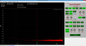
I made some more experiments with the idle.
Unless the output is really cranked up there is not much change in the distortion spectrum.
At least at the level ( ca. 0.5 V ) and load ( 10kOhm ) i am measuring.
For the time being i settled on 120 Ohm and 12 Ohm.
I also build in the MosFets but sofar i can not make it work.
Because i am lazy i did not build Frans version with the higher resistor values but kept the values from the BJT version, like Calvin did in his last post.
Anyone an idea what could have going wrong ?
I have the Mosfet version working.
I think what went wrong is that the N-channel belongs in the positive feed ( top ) and the
P -channel belongs in the negative feed ( down ).
Unfortunately i get a lot of distortion so something is not right.
I think what went wrong is that the N-channel belongs in the positive feed ( top ) and the
P -channel belongs in the negative feed ( down ).
Unfortunately i get a lot of distortion so something is not right.
You are so welcome 🙂
Hope I was there.