I did compare both versions.
Sorry, i did not store the measurements of your version.
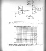
As far as i remember distortion was under -100dB so that is fair.
More then good enough to not cause any audible trouble.
Maybe next time i do it all over again or somebody does a sim.
I usually do design for good PSSR and then use a relativ simple PSU with passive filtering. That is one of the reasons i designed it as is.
The circuit draws only 6mA so i suplly the prototype with lead acid batteries.
Sorry, i did not store the measurements of your version.
As far as i remember distortion was under -100dB so that is fair.
More then good enough to not cause any audible trouble.
Maybe next time i do it all over again or somebody does a sim.
I usually do design for good PSSR and then use a relativ simple PSU with passive filtering. That is one of the reasons i designed it as is.
The circuit draws only 6mA so i suplly the prototype with lead acid batteries.
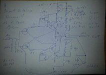
This is the input driven version.
OK, why not using an opamp as buffer anyway that does not have common mode distortion. Even an opamp that has common mode distortion can be compensated by putting a resistor in the feedback loop that has the same value as the driving impedance.
Problem is when you use a pot meter as volume control the output impedance of that pot is changing with volume.
I could imagine a relay based volume control that always has the same output impedance.
Some say discrete sounds better.
Attachments
Hi,
have found something similar, using OPAmp-Buffers:
Elvee and Dadod have shown similar using discretes here
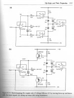
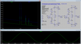
I simmed the circuit with 1Vrms In and working into a 47k/100p load and two issues appeared.
1) Dadod´s as well as Joachims circuit run on very low currents, almost starving. The two emitter resistors toward the output carry less than 1mA. The Elvee/Dadod suffers from the same.
2) Probabely due to the low Bias the THD is considerably higher than the measured values from Joachim (0.023% H3 dominating), reminding not to rely on THD-sims too much 😉 Still though the differences are so large that it makes me wonder about the reasoning.
3) Without the input lowpass filter the amplitude response shows a tendency for ringing (peaking ~10MHz). Only with input filter included the response looked ok.
Played around with the circuits using my favourite SMD transistors and changing to higher Bias levels (~50mA).
Also omitted with the JFET-ccs as a simple resistor instead already profits from bootstrapping action.
With the slight compensation at the bases opf the bootstrappers the amplitude response was free of ringing, already without input filter.
With 1Vrms In and working into a lower 300R/100p (for 600R balanced) load the results were much more like Joachims measurements (0.00011%, H2 dominant).
But try Yourself, the files are attached.
Did also a THD over frequency sim, which showed the same lower THD towards higher frequencies as described in the article above.
jauu
Calvin
have found something similar, using OPAmp-Buffers:
Elvee and Dadod have shown similar using discretes here
I simmed the circuit with 1Vrms In and working into a 47k/100p load and two issues appeared.
1) Dadod´s as well as Joachims circuit run on very low currents, almost starving. The two emitter resistors toward the output carry less than 1mA. The Elvee/Dadod suffers from the same.
2) Probabely due to the low Bias the THD is considerably higher than the measured values from Joachim (0.023% H3 dominating), reminding not to rely on THD-sims too much 😉 Still though the differences are so large that it makes me wonder about the reasoning.
3) Without the input lowpass filter the amplitude response shows a tendency for ringing (peaking ~10MHz). Only with input filter included the response looked ok.
Played around with the circuits using my favourite SMD transistors and changing to higher Bias levels (~50mA).
Also omitted with the JFET-ccs as a simple resistor instead already profits from bootstrapping action.
With the slight compensation at the bases opf the bootstrappers the amplitude response was free of ringing, already without input filter.
With 1Vrms In and working into a lower 300R/100p (for 600R balanced) load the results were much more like Joachims measurements (0.00011%, H2 dominant).
But try Yourself, the files are attached.
Did also a THD over frequency sim, which showed the same lower THD towards higher frequencies as described in the article above.
jauu
Calvin
Attachments
-
 Buffer Bootstrapping 01.jpg410.7 KB · Views: 310
 -
 Buffer Bootstrapping 02.jpg681.5 KB · Views: 322
 -
 Buffer Bootstrapping 03.jpg755 KB · Views: 282
 -
 Buffer Bootstrapping 04.jpg618.4 KB · Views: 272
 -
Bootstrapped crosscoupled Diamond Buffer.asc8.2 KB · Views: 105
-
Bootstrapped crosscoupled Diamond Buffer - JG.asc8.9 KB · Views: 109
The 4th (op-amp) circuit looks nice, but using both op-amp's in inverting mode at each halve the gain will give, the same noise (about), higher BW, better slewing and no input differentials (thus no need for bootstrapping). All-in-all a better circuit with less components.
Yes Calvin, this are the circuits from Self i talked about.
I will look at your improved circuit later on my lab computer.
I can not open an .asc file on my Mac.
Frans, inverting solves the common mode problem ( mostly, some opamps still show common mode distortion, even inverted, see Groner ) but may have a disadvantage in noise because the nesesarry input resistors are in series with the signal.
Also when you want a high input impedance the series resistors have to be even higher making the noise even worce.
Yes, one should use low resistor value's. If this is not possible then (and only then 🙂 IMO) use a non-inverting circuit (or a simple JFet buffer (I have to think about this)).
At line level the noise of a modern op-amp circuit is at -120dB or better.
At line level the noise of a modern op-amp circuit is at -120dB or better.
Last edited:
I can not open an .asc file on my Mac.
You need to get the LTspice version for Mac.
Linear Technology - Design Simulation and Device Models
I can not run the simulation of both files. LTSpice does not find the models of the input transistors.
Anyway, i see the major difference is that you use higher idle.
When you look at my original circuit i also have compensated the bootstrap transistors.
Without the circuit oscillates. I saw that on the scope.
During development i also tried a version with more idle at the output.
I used BC140, BC160 with 4.7 Ohm emitter resistors.
Couriously it did not work.
Maybe i had a bug.
I see that you take the bootstrap direct from the emitters.
Does that make a difference ?
You are using 100uF over the 27kOhm resistors.
I persume to improve the performance in the bass.
This can then only be an electrolytic.
What should the lowest value be so that i can use a film cap ?
I may try a compromise by raising the idle in the circuit i have.
My Mac is too old to run the current LTSpice version.
Not a big problem. I have a Windows 8 laptop in my lab.
Not a big problem. I have a Windows 8 laptop in my lab.
Hi,
here are the models included 😉
They are from Bob Cordell and Fairchild Website.
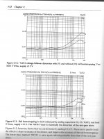
I changed the Emitter resistors to values such that the Output Transistors idle around some 6mA.
With these values, THD distribution and -level is more like Joachim´s measurements.
jauu
Calvin
here are the models included 😉
They are from Bob Cordell and Fairchild Website.
I changed the Emitter resistors to values such that the Output Transistors idle around some 6mA.
With these values, THD distribution and -level is more like Joachim´s measurements.
jauu
Calvin
Attachments
I measured the idle of the output transistors in my actual build.
It is 1.5mA.
I will now rebuild to the circuit of post 9912 and measure again.
It is 1.5mA.
I will now rebuild to the circuit of post 9912 and measure again.
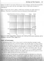
Using a small mosfet for the cascode reduces the signal difference from 1.6Vac to 170uVac (between cascode output and buffer output) this lowers the distortion significantly.
Which difference?
Please clarify.
Frans, pretty cool.
Could ZVN3306A and ZVP3306A being used ?
Yes you can 🙂
Which difference?
Please clarify.
A 'perfect' cascode should show a 0Vac difference between it's input and it's output (even a 0Vdc difference 🙂). In this case the AC difference between the cascode output and the buffer output is the important one 🙂
Hi,
in sim the ZVP3306A/ZVN3306A work alot better than the bipolars, and also work better than the BSH/BSS.
Besides the bias-mod, take a look at the Gate compensation networks.
Seems the caps could be reduced in value.
In sim the 100nF lead to a ~0.2dB loss above 1kHz.
Is the C1 a stabilizing Lytic between the two cascode feeding points?
jauu
Calvin
ps. We are the champions .... and tonight we´ll become soccer Champions too. 😀
Attachments
Last edited: