Do you use the IR/Vishay IRFP9240 that has the odd performance curves?
Others are near impossible to find from reliable sources.
Others are near impossible to find from reliable sources.
Do you use the IR/Vishay IRFP9240 that has the odd performance curves?
Others are near impossible to find from reliable sources.
I use only IR mosfets.
Attachments

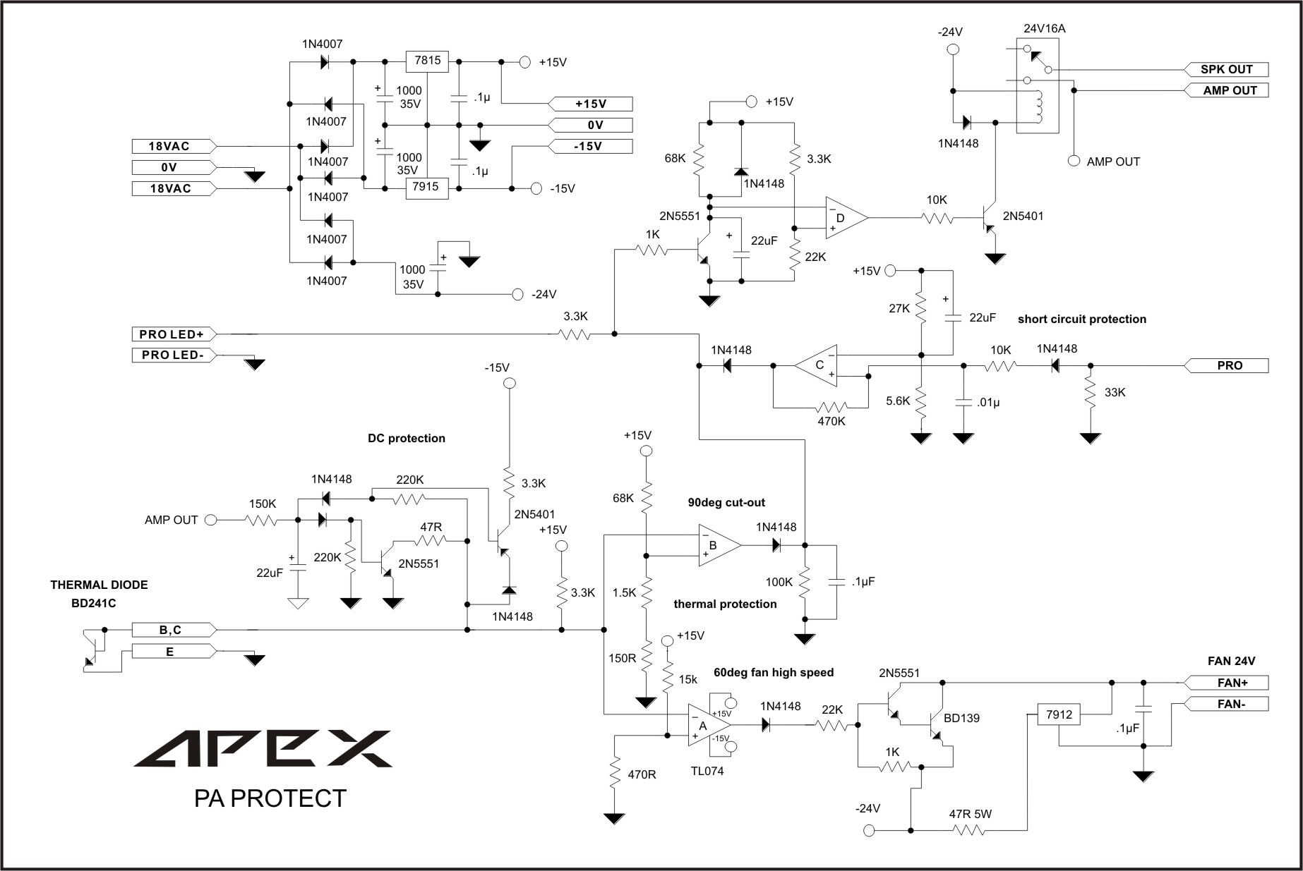
apexaudio, I corrected your diagram above. It's better that way.
And I don't think the PEAK circuit is calculated or work correctly!!
And I don't think the PEAK circuit is calculated or work correctly!!
Attachments


Last edited:
apexaudio, I corrected your diagram above. It's better that way.
And I don't think the PEAK circuit is calculated or work correctly!!
PEAK LED will light on if voltage on amp out increase about 6-8V up to rail voltage, it's correct for me.
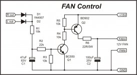
No need to change fan control circuit, corrected or not it will work anyway.
Please answer me
 Please rephrase your question in comprehensible English and someone might be able to answer you. Right now no one has any idea what the question is you asked.
what is this the pro on the schematisc?
An externally hosted image should be here but it was not working when we last tested it.
Last edited:
what is this the pro on the schematisc?
An externally hosted image should be here but it was not working when we last tested it.
Well, Pro is short term of Protection. It's an over-current detector and in case of short circuit on the output, it sends the error signal to the protection board.
Attachments
My email id bushulo@gmail.com if someone could kindly send me the gerber files or pdf of HV350.2 PCB layout.
Thank
Thank
dear bushulo,
do you have obtain gerber files or pdf of hv350.2 pcb.i live in lucknow by this locotion i came to know that you belong to goa .i recently make a tour for goa,staid at hotel goa international in panji at meer mar beach.by the way it is very pleasant city i am too impressed with this city.my English is poor plz not mention.thanking you.my e mail is alvi.masood251@gmail.com
do you have obtain gerber files or pdf of hv350.2 pcb.i live in lucknow by this locotion i came to know that you belong to goa .i recently make a tour for goa,staid at hotel goa international in panji at meer mar beach.by the way it is very pleasant city i am too impressed with this city.my English is poor plz not mention.thanking you.my e mail is alvi.masood251@gmail.com
Hello Mile,
Could you explain working of circuit in post 383 so we can adapt it to other amplifiers? How is the overload/short circuit detected? What current?
Regards,
Victor
Could you explain working of circuit in post 383 so we can adapt it to other amplifiers? How is the overload/short circuit detected? What current?
Regards,
Victor
hello, is it safe to use 2x63V for 3 pairs of IRFP240/9240? This should give about 250W to 4 ohms. There is no problem at 1khz and 10khz, but when we go close to limitation at 100hz in 4 ohms, then all IRFP240 burn. Maybe these transistors are fake?
3pr of 240/9240 adds up to ~900W of output devices.
Divide by 4 for MosFETs and you get ~225.
Your target of 240W into 4r0 is close enough to 225 to be considered as reliable.
However, your target of 240W and +-63Vdc do not seem compatible !
Divide by 4 for MosFETs and you get ~225.
Your target of 240W into 4r0 is close enough to 225 to be considered as reliable.
However, your target of 240W and +-63Vdc do not seem compatible !
I get 300W to 320W from +-58.5Vdc supply rail using BJT output stages.
A mosFET output stage may require upto 5V more on the supply rails to achieve that 300 to 320 target.
But you are showing a target of "only" 240W from supply rails that are 4.5V higher. That seems odd.
A mosFET output stage may require upto 5V more on the supply rails to achieve that 300 to 320 target.
But you are showing a target of "only" 240W from supply rails that are 4.5V higher. That seems odd.
- Home
- Amplifiers
- Solid State
- MOSFET Amplifier IRFP240/IRFP9240