Any one know where I might find schematics, service or operations documentation for this monster amp?
I'd love to build one in 2010...
I'd love to build one in 2010...
I have schematic of 10KW and 30KW vacuum tube amps lying somewhere 🙂 Would be kinda expensive to run and listen music, especially on headphones 🙂
Well ! that is a bit much for a modest listening area, 10KW/30KW audio power is probably better suited for a stadium sized event.
And both would be a bit harsh on the power bill. Still I'd love to see what makes one tick.
All things considered, leaning towards practically I think a more realistic design would be something in the 200 to 500 watt per channel range.
thanks
And both would be a bit harsh on the power bill. Still I'd love to see what makes one tick.
All things considered, leaning towards practically I think a more realistic design would be something in the 200 to 500 watt per channel range.
thanks
If I'm not mistaken, some of those amps were used at Indy for the race track there back in the 60s! As I recall, they still could have used a few more!!!!
Dave
Dave
All things considered, leaning towards practically I think a more realistic design would be something in the 200 to 500 watt per channel range.
You'd still need a bigger room! I've recently gone from a 150W class A transistor amp to a 13W SE tube amp, and haven't noticed any lack of volume - in fact a bit more punch and bass!!
I have a friend who used to work there too who has built a moonbounce transmitter. It runs 6 X 2C39 tubes (external anode) with 1800 volts on the plates. The plates are screwed directly into an aluminum heat exchanger which is cooled by water. He says that he changes the water every month or so.
EME is some seriously fun-looking stuff. Wouldn't mind trying to put together an array once I get my own place 😀
EME is some seriously fun-looking stuff. Wouldn't mind trying to put together an array once I get my own place
My original EME plans were thwarted by the local code enforcement cops forcing me to remove all antennas from my property even the TV antenna about 15 years ago. I still plan an assault on the 902 MHz EME record some time before I die or leave south Florida. I have collected equipment capable of generating over 1KW of RF power at 902 MHz, but it is all solid state. The antenna will be a 12 foot or larger dish.
And both would be a bit harsh on the power bill. Still I'd love to see what makes one tick. All things considered, leaning towards practically I think a more realistic design would be something in the 200 to 500 watt per channel range.
Its on the back burner but I will build something in the 200 to 500 watt power range someday, probably long before the EME device, just because it is far easier. First off as I mentioned earlier in the thread ignoring the practical aspects the total power output of any amplifier is limited its efficiency and the available input power from the wall outlet. A wall outlet in the US is rated at 15 amps and 120 volts for a maximum input power of 1.8 KW. Assuming an overall efficiency of 50% we are limited to 450 WPC. OK, loud enough to wake the neighbors.
So we want a 200 to 500 WPC amp. There is more than one way to get there. As mentioned before transmitting tubes like the 813 that were intended for modulator use can be used to build audio power amps in the 1KW+ range. To get big power from transmitting tubes requires a lot of voltage and a fairly high load impedance, maybe 10K ohms. A 500 watt OPT at 10K ohms that can cover the entire audio range will be tough to design and not cheap.
Another way, and the typical way for big guitar amps is to parallel several audio tubes like the 6550 to get 300+ watts. The typical load impedance here is 1250 ohms and OPT's are off the shelf from Hammond, Plitron and others. Google up the schematic for the Ampeg SVT to see a 300 watt bass guitar amp that makes 300+ watts with 6 X 6550.
Yet another way is to use multiple sweep tubes. Sweep tubes support higher peak currents than the typical audio tubes and usually offer a bit higher efficiency. Many can be driven through the screen grid for even higher efficiency. Impedances are similar to (maybe a little lower) the 6550.
Experiments with Petes red board running on external power supplies has led me to believe that my amp will use sweep tubes, probably 4 X 6LW6 per channel. I was able to extract 200 WPC from Petes board using 2 6KD6's per channel from 600 volts. Several examples of power levels in the 100 to 240 WPC can found throughout the thread starting from post #218. This was all done with a PC board that was intended for 20 WPC.
Next up I will create my own board using knowledge gained from experiments on the red board combined with my own ideas like PowerDrive to create a test board for even higher powered experiments. I have very limited time right now, so it won't be any time soon though.
First I heard of that, I got two 18 kw heating coils in my home heat pump air conditioning system operating on single phase 234VAC. So who's going to pay for the three phase feed into my home? The government?Tubelab maybe its time to switch to 3 phase wall outlet.In USA(110v) ewerything that exced 500w continous consumpsution must replaced with 3 phase suply(3x200V).Here in Europa (220v)ewerything over 1KW must be replaced with 3 phase main nec(3x380v).BTW many advantages 3 phase primary/3 phase secondary Psu have😛ulsating freqency from full wave rectifier its 360 hz(USA) so smothing fillter is not so critical in comparison with 120 hz from monophase(110v).Comon primary curent is divided in 3,plus primary voltage is not 110v but 3x200v(Primary curent more down)IN extreme cases it is posible to have 3phase primary and 4phase secondary from same transformer.One of the tube which I recomend for High power SE or PP is tetrode QB5/1750(got wery good expirience from high power AM transmitter with this tube).5,6 KV UBA and ower 5KW output with 4 tubes).Or Rusiann big power pentode GU81M.Salute Tubelab
Tubelab maybe its time to switch to 3 phase wall outlet.In USA(110v) ewerything that exced 500w continous consumpsution must replaced with 3 phase suply(3x200V).
So who's going to pay for the three phase feed into my home? The government?
The government? With whose money? The taxpayers? No. We are all out of money. No one, because it simply isn't going to happen. There are plenty of more important problems in the US that electrical power.
Three phase distribution is common across the US, but 3 phase power isn't delivered to individual homes anywhere in the US that I have visited. Trust me I spent a lot of time following power lines during the three weeks we were without power after hurricane Wilma. The power lines from my house are single phase all the way back to ther main street entering out neighborhood. To make that 3 phase would mean upgrading 90% of the wiring in the neighboorhood. FPL hasn't even fixed the stuff that was patched after the hurricane 5 years ago.
Tubelab: This falls under the category of don't get us started right? Not rewire the neighborhood, rewire the Nation. Most residential transformers are 7200 or 12500VAC AUTOTRANSFORMERS. There ain't but one hot and one grounded leg. The 234VAC is taken from wider apart on the winding. They are the same leg, just separated by turns of wire. No relationship to windings on the turbine generator back at the power plant.
That rule was probably part of the Kyoto or Copenhagen accords. Which reminds me, time to reload my lip.....
That rule was probably part of the Kyoto or Copenhagen accords. Which reminds me, time to reload my lip.....
There were plate modulated "Clear Channel" stations running 50KW back in the '50s. They must have been using some sort of modulator tube. I dunno what, maybe racks and racks of Parallel Push Pull 833 or similar triodes? But why? What sort of transducers would you use. Old Altec Stadium equipment was too effecient. Build Electrostatic panels 200' high and 100' high? You'ld still need a subwoofer. hehhehhehhehheh Then your mayor would really have something to complain about.
I know; ten thousand Lowthers in line a array.
I know; ten thousand Lowthers in line a array.
Last edited:
I've heard dub sound systems pushing out 30K watts but that's MOS-FET, what do you reckon you'd need need for a hall (and then some)?
Not rewire the neighborhood, rewire the Nation. Most residential transformers are 7200 or 12500VAC AUTOTRANSFORMERS. There ain't but one hot and one grounded leg. The 234VAC is taken from wider apart on the winding.
Yes, this is true, but the HV transmission (UHV to the substation) and distribution (HV from the substation to the neighborhoods) IS three phase. That is why you see the distribution poles carrying groups of 3 wires. To make 3 phase power available to a customer ALL 3 WIRES need to be present and 3 of the transformers you describe are used. This is how the shopping center at the entrance of the neighborhood gets its 3 phase power. All three distribution wires run down the center of the neighborhood, however only ONE wire runs down each block (1/4 to 1/2 mile) so 3 phase power to the individual homes is not possible.
Are you sure about this ? My neighborhood had pse out replacing wire (underground) about a year and they were running 3 separate wires to the home's distribution step down transformers.
1kw amp for a home might be over kill since you'd need 2 for 2 channel audio, and I can only guess what the power requirements would be. how about something a bit more realistic? a schematic for a 200 to 500 watt per channel tube amp using parts available... class A if possible
thx
1kw amp for a home might be over kill since you'd need 2 for 2 channel audio, and I can only guess what the power requirements would be. how about something a bit more realistic? a schematic for a 200 to 500 watt per channel tube amp using parts available... class A if possible
thx
Tubelab,
I spent the first 25 years of my life in South Miami 2 blocks from the old Parrot Jungle. Graduated from Palmetto Senior High.
I do not remember any classes being available at that time in public school which would have offered electronics and HiFi construction. Which school did you go too. It would have been a much more enjoyable education experience building tube amps and such. We had an automobile and woodshop class and that was it for vocation in high school.
On the subject of cooling the tubes for a high output amp something on the line of R-22 or R-134 using a change of state and transferring the heat outside is very feasible. A small junked refrigeration compressor and large condenser would suit the bill. Make some copper coils to encase the tubes and so on. I guess that would be a nice project for when we retire. Not enough time in the day for work, chores and hobbies.
Tad
Yes exotic cooling is a possibility, I've seen and read about where some fanatic used liquid nitrogen to cool their computer project and was able to over clock the machine to 5 gig or so. But one must consider the practically of this. I'd like to build an amp that doesn't require these measures to run on a day -to- day basis. Which is why I want to scale back on the amp's output power to more realistic level. If 2 7591's can provide approx 40 rms, then can 4 = 80, and 8=160 ?
But connecting many output tubes in a circuit sounds iffy. I'm sure there is a better way
Any one know of schematics for a amp in this size?
But connecting many output tubes in a circuit sounds iffy. I'm sure there is a better way
Any one know of schematics for a amp in this size?
Are you sure about this ? My neighborhood had pse out replacing wire (underground) about a year and they were running 3 separate wires to the home's distribution step down transformers.
I am sure that there are scattered places in the US where 3 phase power is available, but it is not the norm. As I mentioned previously I had a friend who lived near an industrial park where the 3 transformers were close by. FPL refused to install 3 phase even if he paid for the installation. It seems that they have no means for billing for it in residential areas. Many large facillities with 3 phase power get charged a different rate per KWH at different times of the day.
1kw amp for a home might be over kill since you'd need 2 for 2 channel audio, and I can only guess what the power requirements would be. how about something a bit more realistic? a schematic for a 200 to 500 watt per channel tube amp using parts available... class A if possible
I know some people who have Carver 2 KW amps in their homes. In fact I had a Crown CE2000 which was rated at 1.9 KW. One channel was dead but the working channel blasted my 15 inch subwoofer into oblivion. I used it with a guitar preamp to really annoy my neighbors, but got tired of it and gave it to another forum member who wanted to fix it. My lab / listening room is only 10 X 11 feet. Even with 87 db speakers I routinely use a 45 based SE amp that makes 2 WPC. A 50 WPC amp is overkill for me, but....
I have a pair of Plitron toroidal OPT's that are rated for "400 watts at 20 Hz". I have a pair of Antek 4TK400 power transformers that will deliver 1KW of continuous power (I'll get more if I need to). I plan to use these and some tubes that I already have to make an amplifier that delivers from 200 to 500 WPC. Exactly how much power is not important to me, I just want to effectively use the parts that I already have.
It should be noted that "realistic" "200 to 500 watts" and "class A" are somewhat mutually exclusive terms. By definition class A amps are not efficient. SE class A amps are usually from 5 to 10% efficient and P-P class A amps might see 20%. Too much energy is converted to heat, and dozens of tubes will be needed to get to 500 WPC. My amp will likely run AB2, but like all class AB amps there will be a region of power where the amp remains in class A. For an amp of this magnitude that should cover all normal listening levels.
Tubelab,
I spent the first 25 years of my life in South Miami 2 blocks from the old Parrot Jungle. Graduated from Palmetto Senior High.
I do not remember any classes being available at that time in public school which would have offered electronics and HiFi construction. Which school did you go too.
I grew up in South Miami just west of UM. I went to Southwest High, a few miles north of Palmetto. We had an entire wing of the school devoted to vocational education. There was auto shop, commercial art, cosmetology, wood shop, machine shop, electricity and HVAC, and electronics. This was 1967 - 1970. Many of these classes closed down not too long after I graduated. The electronics class that I took was a 3 year program that was 3 hours per day for the last 2 years. It was heavilly oriented toward TV repair. Both instructors were ex military with minimal teaching experience. Our class room was huge and we were always getting tons of stuff donated by local businesses and Homestead AFB. We even got stuff from Coulter and Milgo that contained transistors and IC chips. Of course tons of TV's and tubes. There were 3 of us who knew as much as the teacher, so we got to play with the "stuff" and ocassionally demonstrate and explain our findings to the class, and to the other class (there were two, one in the morning, and one in the afternoon).
I worked at the Olson Electronics store on US1 near UM from 1970 - 1972. I got a job at Motorola in Ft. Lauderdale in 1973 where I still work today. The vocational electronics program was still running in 1973 which was the last time I visited, but the teacher was thinking about retiring. I think it shut down when he left.
In a very general sense power output goes up proportionally with the number of tubes used, but it's difficult to get lots of devices in parallel to share the load equally. Without careful design / matching, the ones with more gain tend to hog the load while the others loaf..
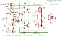
300WPC push-pull amp with only 2 stages ;-)
Here is a work in progress. I have a pair of 300W OPTs made by AES, supposedly from a Cary amplifier. They have 8K plate-plate impedance, and after a lot of deliberation this is how I am using them.
The 4CX250 and relatives have 250W anode dissipation and gm of >20 mA/V. Versions are available that use forced air cooling, water cooling, or conduction cooling, that I know of.
I found a small blower that can be operated at low speed which should be able to cool all 4 tubes up to about 150W anode dissipation each (at 300WPC output). Maybe it can have a simple thermal speed control. For me it's a decent tradeoff. The amp is in a fully enclosed chassis and the blower is down in the guts of it.
The relatively low g2/g1 mu of 5, and the decent grid power ratings make the 4CX250 a good candidate for scaled grid drive.
The asymmetric pentode/MOSFET LTP splitter with feedback loading is intended to use extra second harmonic in the driver to cancel some of the inherent third harmonic of the output stage, hopefully with tweaking to produce a nice waterfall with dominant 2nd. Scaled grid drive should be quite linear anyway.
Cheers,
Michael
Yes exotic cooling is a possibility, I've seen and read about where some fanatic used liquid nitrogen to cool their computer project and was able to over clock the machine to 5 gig or so. But one must consider the practically of this. I'd like to build an amp that doesn't require these measures to run on a day -to- day basis. Which is why I want to scale back on the amp's output power to more realistic level. If 2 7591's can provide approx 40 rms, then can 4 = 80, and 8=160 ?
But connecting many output tubes in a circuit sounds iffy. I'm sure there is a better way
Any one know of schematics for a amp in this size?
Here is a work in progress. I have a pair of 300W OPTs made by AES, supposedly from a Cary amplifier. They have 8K plate-plate impedance, and after a lot of deliberation this is how I am using them.
The 4CX250 and relatives have 250W anode dissipation and gm of >20 mA/V. Versions are available that use forced air cooling, water cooling, or conduction cooling, that I know of.
I found a small blower that can be operated at low speed which should be able to cool all 4 tubes up to about 150W anode dissipation each (at 300WPC output). Maybe it can have a simple thermal speed control. For me it's a decent tradeoff. The amp is in a fully enclosed chassis and the blower is down in the guts of it.
The relatively low g2/g1 mu of 5, and the decent grid power ratings make the 4CX250 a good candidate for scaled grid drive.
The asymmetric pentode/MOSFET LTP splitter with feedback loading is intended to use extra second harmonic in the driver to cancel some of the inherent third harmonic of the output stage, hopefully with tweaking to produce a nice waterfall with dominant 2nd. Scaled grid drive should be quite linear anyway.
Cheers,
Michael
Attachments
Last edited:
Todd,
Mcintosh was getting over 500 watts from 8 6551 tubes back in the late seventies, from the mc3500, with no external cooling. Your idea is very doable. I think the mi200 was using only one large tube. Finding iron today will cost a fortune unless you roll your own.
Do you have any schematics in mind? I am about ready to move on from sand to glass. I like the p2p wiring.
Tubelab,
1970 was the same year I graduated from Palmetto High-- one small world. I remember hearing about the vocational classes offered at Southwest. You guys had a huge area for that kind of stuff. Kind of like the area for hard cases at my school.
Remember the huge rockpit over there just off of Gallaway Drive. There were 4 in the vicinity. Crystal clear natural water nothing added.
Tad
- Status
- Not open for further replies.
- Home
- Amplifiers
- Tubes / Valves
- Monstrous 1kW amp!