Nelson Pass said:It's very easy to cascode the rails of the op amp so
as to support high amplifier rails if you like.
Yes, i did that already, I think in all of my high power versions.
But the output of the opamp can only swing up to the opamp rails.
And for a single ended or push-pull classA with 24V rails there is another gain stage needed.
So the advantage of the use of opamp fades away...
Or do I miss something ?
Typically this is why you see a voltage divider from the output
of the amp to the output of the "input opamp", so that it
does not have to swing full output.
of the amp to the output of the "input opamp", so that it
does not have to swing full output.
Source follower
Nelson and others,
What do you think about this design?
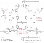
I just wanted to put two source follower after the lm6181 and so output stage will work in classA. All the voltage gain is done by opamps and current gain by follower.
The power is 25Wrms limited by the 10Vmax output of lm6181.
Thanks
Hugo
Nelson and others,
What do you think about this design?
I just wanted to put two source follower after the lm6181 and so output stage will work in classA. All the voltage gain is done by opamps and current gain by follower.
The power is 25Wrms limited by the 10Vmax output of lm6181.
Thanks
Hugo
Attachments

Hi Hugo,
very nice !
Did you notice this schematic in post #778 with dynamic current source ? 😉
By the way1), as in your and my schematic, the LM will need to have a positive offset to drive the gate of the fet to have 0V output.
So voltage swing is limited further.
A resistor from LM output to gate and another resistor from gate to V+ will cure this.
By the way 2), the rails of the op amps may be modulated by another amp, so the rails of the LM could be virtually +/- 24V.
This looks complicated but it is very simple.
The classA/B amp drives virtual ground of LM, allowing rails like +/+15V @ idle and for example +20V/-10V @ positive signal 😀
And drives virtual ground of SE classA outputstage allowing low voltage rails & low dissipation. 😀
I will apply this to my distortion killer circuit as well. 😀

Greetings, Bernhard 🙂
very nice !
Did you notice this schematic in post #778 with dynamic current source ? 😉
By the way1), as in your and my schematic, the LM will need to have a positive offset to drive the gate of the fet to have 0V output.
So voltage swing is limited further.
A resistor from LM output to gate and another resistor from gate to V+ will cure this.
By the way 2), the rails of the op amps may be modulated by another amp, so the rails of the LM could be virtually +/- 24V.
This looks complicated but it is very simple.
The classA/B amp drives virtual ground of LM, allowing rails like +/+15V @ idle and for example +20V/-10V @ positive signal 😀
And drives virtual ground of SE classA outputstage allowing low voltage rails & low dissipation. 😀
I will apply this to my distortion killer circuit as well. 😀
Greetings, Bernhard 🙂
Thanks for answering me so fast.
I saw your post but I think that simpler it is better it work thats why I don´t want to make active current soursing and try to work only with constant courant source. I know that in this way it's going to warm a lot, but I like it...........
Do you think it's going to work well???????
I saw your post but I think that simpler it is better it work thats why I don´t want to make active current soursing and try to work only with constant courant source. I know that in this way it's going to warm a lot, but I like it...........
Do you think it's going to work well???????
Excuse me bernhard, I didn´t see the end of your answer.
I think it´s not very important to have DC on output if we have enough Voltage on rail, because we work in symmetrical way. So If there is 0V on the gate of the mos, there will be -3V or -4V on the output. But we have the same thing on the other output, so the loudspeakers will see a differential offset of 0V. Of course we have to be sure that the mosfets are good matched.
Best regards
Hugo
Hugo,
its just two resistors that eliminate the offset...
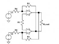
You could make the Aleph-X without active CS too
I have to look at the A-X and try to understand it, I was always too much occupied by my own circuits, so couldn't do it yet.
To me it looks like your schematic works, just the the values of the z-diode 6,2V seems to be a little high, but I can not read the values of the 0,?? ohm resistors.
I am looking forward to your comment about the distortion of A-X and NMDKC*
Bernhard
*No Mercy Distortion Killer Circuit
its just two resistors that eliminate the offset...
You could make the Aleph-X without active CS too
I have to look at the A-X and try to understand it, I was always too much occupied by my own circuits, so couldn't do it yet.
To me it looks like your schematic works, just the the values of the z-diode 6,2V seems to be a little high, but I can not read the values of the 0,?? ohm resistors.
I am looking forward to your comment about the distortion of A-X and NMDKC*
Bernhard
*No Mercy Distortion Killer Circuit
HI bernhard
I didn't understand where are the resistor that kill offset on your shematic. You're speaking about a resistor from LM output to gate, I don't see it, and another from gate to V+, I don't so it too........
Thanks and merry Christmass to everybody.
I didn't understand where are the resistor that kill offset on your shematic. You're speaking about a resistor from LM output to gate, I don't see it, and another from gate to V+, I don't so it too........
Thanks and merry Christmass to everybody.
Hi Hugo,
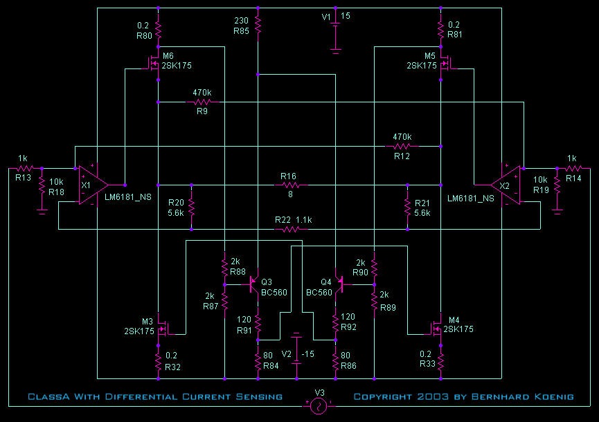
in the big schematic, its R15/R9 for the SE classA gain fet.
R7/R2 are for the upper classA/B fet and R33/R44 for the lower classA/B fet. They have no influence.
On the LM output is 0V.
Merry Cristmas,
Bernhard
in the big schematic, its R15/R9 for the SE classA gain fet.
R7/R2 are for the upper classA/B fet and R33/R44 for the lower classA/B fet. They have no influence.
On the LM output is 0V.
Merry Cristmas,
Bernhard
Hi everybody........
I had a new idea..... I think that the thing that introduce the most distortion is gain stage. So why not doing a gain stage with lm6181 and just 2 symmetrical follower.... Just an idea.... I attach a shematic but in ps format, I hope you can read it.
Thanks
Hugo
I had a new idea..... I think that the thing that introduce the most distortion is gain stage. So why not doing a gain stage with lm6181 and just 2 symmetrical follower.... Just an idea.... I attach a shematic but in ps format, I hope you can read it.
Thanks
Hugo
Attachments
Hugo,
now the gain stage is outside the feedback loop...
The susy will have zero effect.
There will be high offset on both sides, maybe compensating each other.
No higher order distortion from the gain fets, could be good.
But still from the feedback loop of the LMs.
I tried that with my distortion killer circuit, left side output stage was not inside the feedback loop, I have to re-check behavior on higher order harmonics, but K2 and K3 was worse.
Bernhard
Hi Hugo in Paris,
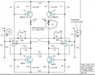
With my amp, I am using the supply currents (Is) of LM6181, i.e. through the pin 4 and 7, to create the transitor's base current for both the bias and the sound signal. I hope this info will be helpful.
All the best.
With my amp, I am using the supply currents (Is) of LM6181, i.e. through the pin 4 and 7, to create the transitor's base current for both the bias and the sound signal. I hope this info will be helpful.
All the best.
As Nelson Pass and other experts say: “The greater, the better,” ...
In order to increase the amount of bias current from about 20mA to about 28mA through each MOSFET, I added 100 ohm registers running parallel across 32 ohms. Of course, this makes Vds value (Q) lower from about 19Vdc to about 13Vdc across the signal-amplifying MOSFET, and the lowered 13Vdc could be technically too low with respect to linearity.
Nevertheless, after having this, if the music is a TV-screen, I feel that the screen is getting larger, gaining warmer air but without loosing details. Could my feeling be just an illusion?
JH
PS/ I have no idea about signal distortion value at all.
Attachments
Hi, JH,
Do your current sources (sinks) actually attach to the positive rail as shown in the diagram?
Erik
Do your current sources (sinks) actually attach to the positive rail as shown in the diagram?
Erik
- Status
- Not open for further replies.
- Home
- Amplifiers
- Pass Labs
- Monolithic SuperSymmetry with Current Feedback