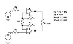
I don't know that it is better or not, but the first is
Super-Symmetric and the latter is not. Any distortion
occuring in 1 op amp will be reinforced by the other,
not cancelled.
Super-Symmetric and the latter is not. Any distortion
occuring in 1 op amp will be reinforced by the other,
not cancelled.
Mr.Pass,
With regard to the second diagram (non-super symetric). How would you characterize it's performance with a balanced input as opposed to using two independant amplifiers each with R1 attached to ground (not sharing feedback resistor R1).
Regards,
Jam
With regard to the second diagram (non-super symetric). How would you characterize it's performance with a balanced input as opposed to using two independant amplifiers each with R1 attached to ground (not sharing feedback resistor R1).
Regards,
Jam
Hi,
I have finally read every post in this thread, and I'm going to bed! It's 3:15am and I have a presentation at 12:00pm on my dissetation. I would like to say a huge congrats to everyone - truely inspirational...I am thinking about a PCB version based on JH's circuit.
Can you run it with +- 30V rails?
Thanks,
Gaz
Yeah... it’s been one year since I joined in this project.
It seems that, developing my project, I have learned lot of basics about electronics, mmm... not theoretically but practically. Of course, among others I have much enjoyed in developing of the project.
I have used my amp almost every day for one year, watching out carefully about any symptom of technical problems. I have however not noticed any sign of trouble. Now I would like to give it a full trust.
I have set up my amp with BOSOZ, both of which are the latest versions. I usually listen to the music sourced from Marantz CD player SA-14 and the movie track sound sourced from Denon DVD player 2800. The sound? Not the best, but nice sound.
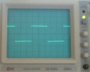
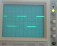
My latest circuit diagram is shown below. First, I have checked output nodal DC voltages at the speaker terminals and found them less than 80 mV. I have also checked differential offset DC voltages and found within 30 mV. I inform you that I have not carried out any component matching for this project. Then, after grounding ?input, and with unbalanced source, I have measured square waves at the speaker terminals at 100, 1K, 20K and 200K Hz. The wave forms are found entirely clean. (I will post the pictures as soon as I fix my D-camera.) In addition, I have measured symmetrical clipping.
Now, I am motivated to invite any of you to share this amp with me, and I would like to share our opinions.
Regards
JH
Oh...! Mr Nelson Pass, again thanks you very much for your inspiration of this project and your kind instruction. I sometimes listen to Goldfrapp, 😉 though...now listening to Alanis Morissette MTV Unplugged... Damn it! One week holiday is too short...^^
It seems that, developing my project, I have learned lot of basics about electronics, mmm... not theoretically but practically. Of course, among others I have much enjoyed in developing of the project.
I have used my amp almost every day for one year, watching out carefully about any symptom of technical problems. I have however not noticed any sign of trouble. Now I would like to give it a full trust.
I have set up my amp with BOSOZ, both of which are the latest versions. I usually listen to the music sourced from Marantz CD player SA-14 and the movie track sound sourced from Denon DVD player 2800. The sound? Not the best, but nice sound.
My latest circuit diagram is shown below. First, I have checked output nodal DC voltages at the speaker terminals and found them less than 80 mV. I have also checked differential offset DC voltages and found within 30 mV. I inform you that I have not carried out any component matching for this project. Then, after grounding ?input, and with unbalanced source, I have measured square waves at the speaker terminals at 100, 1K, 20K and 200K Hz. The wave forms are found entirely clean. (I will post the pictures as soon as I fix my D-camera.) In addition, I have measured symmetrical clipping.
Now, I am motivated to invite any of you to share this amp with me, and I would like to share our opinions.
Regards
JH
Oh...! Mr Nelson Pass, again thanks you very much for your inspiration of this project and your kind instruction. I sometimes listen to Goldfrapp, 😉 though...now listening to Alanis Morissette MTV Unplugged... Damn it! One week holiday is too short...^^
Attachments
jam said:With regard to the second diagram (non-super symetric). How would you characterize it's performance with a balanced input as opposed to using two independant amplifiers each with R1 attached to ground (not sharing feedback resistor R1).
Two independent op amps with balanced inputs will have
lower distortion, but if there is a large DC common mode
input, it will limit the output swing, as this would be reflected
in the output.
Rarkov said:
Can you run it with +- 30V rails?
Problem is that maximum rated supply voltage for LM6181 is +/- 18V.


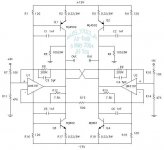
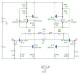
Simple Descrete CFB supersymmetry
Hi All
I have been thinking about posting a design like this ever since Nelson Pass started this thread.
I think it is the simplest form of the CFB supersymmery, almost like a zen amp, but probably too many transistors.
In fact a you could replace the constant currents with globes, to reduce the heatsinking problems and complexity and still achieve a fully balanced design!
The input impedence and gain is low, because i plan to drive it with my enhanced son of zen headphone amp:
http://www.diyaudio.com/forums/showthread.php?s=&threadid=33706
Some people would notice one or two ideas running through my circuits, well i guess am stuck on a theme and seeing how far i can take it.
Another think to note, this design has better specs if a D45H11 is used instead of the mosfets but it may not sound as good. I might try anyway
It probably needs some more work 😉
But Enjoy!
Tim
Intersting:
Not really Monolithic SuperSymmetry with Current Feedback.
Looks like a kind of X-mini (Class A).
Is it right...???
Not really Monolithic SuperSymmetry with Current Feedback.
Looks like a kind of X-mini (Class A).
Is it right...???
It certianly not Monolithic but it is definitely current feedback.
But is it aleph-ish because it uses current sources and not complementary output stages.
But is it aleph-ish because it uses current sources and not complementary output stages.
Probably:
Sister-Aleph-ish because of missing of active current gain...?
Anyhow:
Look forward to hearing from you about the result. Good luck. 🙂 🙂 🙂
Sister-Aleph-ish because of missing of active current gain...?
Anyhow:
Look forward to hearing from you about the result. Good luck. 🙂 🙂 🙂
Thankyou Nelson I appreciate your vote of confidence.
Having a look back at the original post,i have to concede that the circuit is certianly not supersymmetical, but it would seem to be a canditate. This is something I will have to try later.
One question i do have about supersymetry, is the feedback seem to be only negative if the 2 input signals are 180 degs out of phase with each other. But if the signal are in phase with each other (common mode signals) won't they be positively fed back and potentially make the amplifier oscillate?
I am guessing the balancing effect of the R0 (from the circuit in the original thread) will bring it all back under control.
Jh6you:
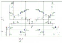
My very next step in the design stage was to use a modulated current source, to improve efficiency and the Nelsons design for the alephs is the one i used.
I guess this design is turning into a Aleph X current feedback varient.
The lastest circuit attached.
Tim
Having a look back at the original post,i have to concede that the circuit is certianly not supersymmetical, but it would seem to be a canditate. This is something I will have to try later.
One question i do have about supersymetry, is the feedback seem to be only negative if the 2 input signals are 180 degs out of phase with each other. But if the signal are in phase with each other (common mode signals) won't they be positively fed back and potentially make the amplifier oscillate?
I am guessing the balancing effect of the R0 (from the circuit in the original thread) will bring it all back under control.
Jh6you:
My very next step in the design stage was to use a modulated current source, to improve efficiency and the Nelsons design for the alephs is the one i used.
I guess this design is turning into a Aleph X current feedback varient.
The lastest circuit attached.
Tim
Attachments
It's an interesting case. The failure to be supersymmetric
is not due to each side not seeing the signal and distortion
of the other half, but rather that signal and distortion are in
phase with each other.
The key trick to supersymmetry is an arrangement where
the differential pair treat signal and distortion out of phase
in relation to each other, that is, they effectively see the phase
of one or the either as inverted. Once you have that, it's very
easy to reinforce signal and cancel distortion. (Or vice versa!)
😎
To whom are interested in:
Reference to the schematics in post#825.
One week ago, I wanted to have a RC-network from the output to the ground because I wanted to tweak the top frequency sound. Recently, I bought a cheap but good Chinese CD player having 6DJ8 at its output stage. It however gave me too much of top end frequencies so that I wanted to make it a bit darker sound by arranging the RC network. But, during my soldering work, I shorted some wires by mistake and transistors were damaged.
Repair:
I went out to the famous Chinese department store selling all sort of electronic components, where I could find out bunch of MJ802 and MJ4502. I bought them, and started to replace all transistors, actually including all others. Finally, I finished this repair and made it into the same as before.
Problem:
By the way, when I was fitting the top cover of the amp a touched the port side heat sink and felt very hot while the starboard side was just warm. I measured DC currents and got 1.2A through the transistors of the left channel, and 0.2A the right channel. Why...???????????? It was OK before with the same circuit and the same component values. All was the same.
Solution:
I thought that problem must have come from the different Vbe of each transistor. Inside the circuit, the different Vbe should be taken into account by chips until the electrical potential equilibrium reaches at the output, and until arrives to this condition, the DC current should flow through the transistors. If so, I might be able to reduce the current by reducing time that takes to reach the equilibrium--i.e. by increasing R15. I increased R15 from 500 to 1K. What happened? The problem gone!!!!! I had both channels with about the same 0.2A. (My explanation might be not professional way from EE's point of view. Give me your kind understanding. 🙂 🙂 🙂 )
RC-network:
I tried it with 1 ohm+0.44uF and 1 ohm+0.22uF. I concluded that with 0.22uF the sound was better.
Picture:
Attached is a picture I took during repair work.
Attachments

- Status
- Not open for further replies.
- Home
- Amplifiers
- Pass Labs
- Monolithic SuperSymmetry with Current Feedback