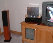
Yeah... Now I am an owner of the small and cute floor-standing speakers, Audio Physic Yara (2.5ways/ 4ohms/ 90dB). I am quite satisfied with them. Even if somewhat missing sharp definition at the bottom end frequencies, they are well balanced overall and good sounding speakers. Really impressed.
They go well with the power amplifier posted just above (Post#780) and BOSOZ.
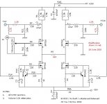
By the way, I have given some more variations to my BOSOZ. I have noticed that BOSOZ has provided better sound when R5 goes lower. I have tried to lower R5 down to 220, but the signal gain has been too much (with weak "sss..." noise from the tweeters). I have fixed my final value with 360, and, to control the signal gain and the "sss..." noise, installed output volume attenuators made with the resistors of 1.5K and 4.7k.
Sweet...
Hoping this info will be interesting...
JH
They go well with the power amplifier posted just above (Post#780) and BOSOZ.
By the way, I have given some more variations to my BOSOZ. I have noticed that BOSOZ has provided better sound when R5 goes lower. I have tried to lower R5 down to 220, but the signal gain has been too much (with weak "sss..." noise from the tweeters). I have fixed my final value with 360, and, to control the signal gain and the "sss..." noise, installed output volume attenuators made with the resistors of 1.5K and 4.7k.
Sweet...
Hoping this info will be interesting...
JH
Attachments
BOSOZ
Hi jh6you
I am currently trying to build your design of BOSOZ with a +/- 50v rail.
But seems that for a +/- 50v rail, my resistor at R1/R2 is alittle under power. I am using a 3 watt resistor.
I don't know what are the various element that I should increase or reduce.
Hope if you are kind enough to give some pointers.
Thanks
CH2
Hi CH2
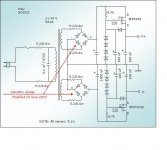
In my circuit, 20mA is flowing through R3 (32 ohms) and accordingly 10mA through each R1 and R2. In this case, R1 and R2 of 0.5W or greater is okay with your +/- 50V supplies.
If you like to increase the 20mA to 30mA (or 40mA), you should reduce R3 from 32 to 22 ohms (or 16 ohms). Still R1 and R2 of 0.5W or greater is fine. I recommend 30mA (or 40mA) bias if you are going to have big enough size of heat sinks.
Hope this will help.
JH
Updating:
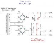
I picked up two 2nd-hand Solen film caps of 1 uF wandering around and was just about to throw away them into the gabage box. No. they were still useful. I was looking around to keep them, but ... where? ... I couldn't find a proper place. What about keeping them inside the power amp? I picked up the solder too.
Yeah... they are quite effective for this amp. The top end frequency edges sound like being smoothed by a very fine sandpaper.
JH
Attachments
jh6you said:
...
I recommend 30mA (or 40mA) bias if you are going to have big enough size of heat sinks.
Hi CH2,
I'm very sorry for my mistake.

I hope you didn't follow my recommendation about the wattage of R1 and R2, particularly in case of the 40mA bias.
Right calculations are as follows:
For 20mA bias, power = 0.01^2*1500 = 0.15W across R1 and R2.
For 30mA, power = 0.015^2*1500 = 0.34W across R1 and R2.
For 40mA, power = 0.02^2*1500 = 0.6W across R1 and R2.
For 40mA, I recommend R1 and R2 @ min. 1W.
JH

jiao liu yi xia (intercommunion)
jh4you:hi
Did you move your Monolithic SuperSymmetry with
Current Feedback amp to shanghai? because i saw chinese word
on tv in the picture you post. if so , maybe sometime you are free,
let us have a talk in shanghai , ok?
jh4you:hi
Did you move your Monolithic SuperSymmetry with
Current Feedback amp to shanghai? because i saw chinese word
on tv in the picture you post. if so , maybe sometime you are free,
let us have a talk in shanghai , ok?
john-china said:
Jiao liu yi xia
Sure, we do (when I fairly settle down myself with this attractive new area).
The amp in the picture is the second one I completed to enjoy it here.
For your info, my place is Min Shi Yuan, Guang Yuan Xi Road, next to Jiao Tong University, in Xu Hui District.

hao(good)
did you build the amp at shanghai? my email is john@trimps.ac.cn, your home in shanghai is close to me,
so easy to contact each other, i am in xuhui district, too.
and what is your email address?
did you build the amp at shanghai? my email is john@trimps.ac.cn, your home in shanghai is close to me,
so easy to contact each other, i am in xuhui district, too.
and what is your email address?
Question about dual CFB Opamps for preamps
Hi, guys.
I visited the National Semiconductor page yesterday, and did a Webguide search here:
http://fuji.national.com/servlet/com.kaidara.kateservlet.questpage.QuestServlet
I typed in only three criteria and made them required (or "MH" for must have, I guess): CFB, 2 channels, and >=15V Max supply voltage.
I hit search, and got 7 results. A few of the amps were pretty expensive, like the CLC431AJ-QML for $22, the CLC432AJ-QML for $23.60, and the CLC431AE-QML for $38.80. I thought they must be really nice, but a bit out of my price range for my purposes.
The cheaper dual opamps I found were more interesting, but they had names that made me think I should ask folks here (Nelson, you out there?) if they will work in the opamp only schematic from post #8:
http://www.diyaudio.com/forums/showthread.php?postid=129639#post129639
They are:
LM359M and LM359N Dual, High Speed, Programmable Current Mode Amplifiers -$about a buck and a half
and
LM13700M and LM13700N Dual Operational Transconductance Amplifiers with Linearizing Diodes and Buffers -$ about half a dollar
Ok, so as I said, they are listed as current feedback *types*, but their titles are a little different, and I just wanted to make sure that the 359 and the 13700 are appropriate for use in in this X circuit?
In particular, I want to get my feet wet designing a microphone level preamplifier and line level amp for a custom mixing board channel. Therefore high power output isn't so much a concern as in the power amps being designed in this thread with fets to supplement the opamps.
Thanks,
Erik.
Re: Question about dual CFB Opamps for preamps
I can only quote Nelson to answer a (small) portion of your question:
/Hugo 🙂
e.lectronick said:Ok, so as I said, they are listed as current feedback *types*, but their titles are a little different, and I just wanted to make sure that the 359 and the 13700 are appropriate for use in in this X circuit?
I can only quote Nelson to answer a (small) portion of your question:
Originally posted by jh6you
Is LM6181 (http://www.national.com/ds/LM/LM6181.pdf) suitable?J
Absolutely, in fact this is the part # I was looking at when
I wrote it up. I recall that there is also a dual part made
by National which might be even more convenient, but I
can't find it now. In any case, any "current feedback" op
amp will probably do the job.
/Hugo 🙂
As soon as my intranet e-mail server is fully transferred here and works stable, I will send you my address. Zai jian.john-china said:
what is your email address?
LM13700 is 36V Max!
Well, the LM13700 has a maximum supply voltage of 36V. It seems like it's a good idea to have a little leeway in tolerances anyway, right? It seems like it'd be perfect!
The more I look at the PDF for it, the more I am convinced it's a great choice. It is indeed a dual current feedback opamp. And the buffers are on seperate pins so you can use them or not. The diodes do appear to be fixed in place on the inputs, but they only look like they serve as overload protection for the input signal I can't see how they'd interfere with X-ing. And you can't go wrong for the price. I'm getting some and trying them out. I'll post my results once I have a suitable test power supply built for them.
-Erik.
By the way, the web address I listed in my previous post seems to have failed to link up to the National Semiconductor Webguide. So, if you just go to
www.national.com
and pull down the menu marked "select", choose "amplifiers", then on the next page click on "webguide" under selection tools, you will be brought to the cool search engine I used. You can punch in any criteria you want on it, and it'll zip you to the best choices for your needs.
Bernhard said:I would be very happy about a CFB that can withstand 24V rails
Well, the LM13700 has a maximum supply voltage of 36V. It seems like it's a good idea to have a little leeway in tolerances anyway, right? It seems like it'd be perfect!
The more I look at the PDF for it, the more I am convinced it's a great choice. It is indeed a dual current feedback opamp. And the buffers are on seperate pins so you can use them or not. The diodes do appear to be fixed in place on the inputs, but they only look like they serve as overload protection for the input signal I can't see how they'd interfere with X-ing. And you can't go wrong for the price. I'm getting some and trying them out. I'll post my results once I have a suitable test power supply built for them.
-Erik.
By the way, the web address I listed in my previous post seems to have failed to link up to the National Semiconductor Webguide. So, if you just go to
www.national.com
and pull down the menu marked "select", choose "amplifiers", then on the next page click on "webguide" under selection tools, you will be brought to the cool search engine I used. You can punch in any criteria you want on it, and it'll zip you to the best choices for your needs.
My Bad...
Whoops, you said rails. I guess I was wrong. it's only +/- 18V. I was reading it wrong.
-Erik.
Bernhard said:I would be very happy about a CFB that can withstand 24V rails
Whoops, you said rails. I guess I was wrong. it's only +/- 18V. I was reading it wrong.
-Erik.
It's very easy to cascode the rails of the op amp so
as to support high amplifier rails if you like.
as to support high amplifier rails if you like.
- Status
- Not open for further replies.
- Home
- Amplifiers
- Pass Labs
- Monolithic SuperSymmetry with Current Feedback