This is largely the result of 10 years of fooling around with the circuit. There is a lot about it that is non-intuitive, and I still find the occasional surprise.Bernhard said:it seems only Nelson knows the answers.
😎
Bernhard said:Whenever there's a door, I will find it 😀
Point me at the door, and I have a selection of big hammers, ( and if that doesn't work, I have a pyro licence😀)
It just came to my mind if not the resistors >gate of the Fets - rails< should be substituted with current sources. 
Bernhard said:It just came to my mind if not the resistors >gate of the Fets - rails< should be substituted with current sources.
No

Bernhard said:
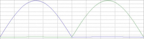
that in the upper 0.XX ohm resistors, the current goes below idle @ negative halfwaves, but not in the lower ones @ positive.
At first look, this circuit behaves like it should.
I'll try some AC analysis next.
The i(R3) and i(R32) plot look normal to me.
/Hugo 🙂
Netlist said:
At first look, this circuit behaves like it should.
I'll try some AC analysis next.
The i(R3) and i(R32) plot look normal to me.
/Hugo 🙂
Did you get the jpg in the first mail ?
i(R3) goes below idle, down to 60mA, while i(R32) never goes below idle of 212mA.
IMHO it is not good for linearity if the Fets conduct less than 100mA current at any time.
The rails of the op amps behave both like i(R32), which means ok.
If you put a 5k between gate of 2sj55 and output, the problem is fixed more or less, but I would like to have a circuit without fixed problems and asymmetric...

This is real complicated.
Isn't it better to do the - I call it " current lifting " now - on both halfwaves, because if it is done only on the halfwave where the Fet can not conduct current, (to keep the current flowing and let the Fet remain in linear mode), the feedback will have to add current on the other side's other halfwave to keep the signal as it should be.
Can you follow me ?
Maybe the sound will be better if the feedback does not have to tweak so much on the waveforms. 🙂
I hope this thread will not become a loud thinking of myself. 🙄
Bernhard, try other mosfets.
I tried the irfp9240 and the irf240 and the idle current is perfectly the same at both positive and negative side but the circuit tends to oscillate slightly.
There must be better pairs. Look what Nelson uses as p and n-mos pairs.
I would use less feedback too.
Also, in your model program, with your circuit loaded, when you click on the icon left from the text icon, the "pin connection" icon, you will see all the nodes displayed. Some wires are too long and tend to make faulty connections. Drag M4 away for example and you will see what I mean.
/Hugo 😉
Netlist said:I tried the irfp9240 and the irf240 and the idle current is perfectly the same at both positive and negative side I would use less feedback too.
Hugo,
did you keep the other values, when changing to irfp ?
I tried that and it gives me no idle at all.
Yes it looks perfectly in the transient analysis, except the crossover distortion
 but with no idle, no wonder...
When You change R2 and corresponding to 560 ohm idle will be about 220mA and the currents through the 0.22 ohm will look even worse with irfp, compared to 2sj/2sk.
Just sides have changed.
One stays at idle and the other really goes down to nothing

Or did I miss something ?
You’re correct, my mistake.Bernhard said:
I tried that and it gives me no idle at all.
When changing R2 and others to 560ohm the whole circuit dissipated 300W

So playing with those resistors will bring the solution.
At 200ohm for R2/R5 and 120ohm for R31/R34 there is a nice idle current of 300mA at both sides.
The fact that those resistors are different in value is due to the use of p and n-mos types IMO.
Not to confuse you, but maybe the difference has something to do with the wiring and components on the negative input of the opamps.
Didn't play with those, so I'm just guessing.
/Hugo
Netlist said:
You’re correct, my mistake.
When changing R2 and others to 560ohm the whole circuit dissipated 300W
Netlist, this can't be true, with 540 ohm I get 220mA everywhere and 22W total dissipation.
Interesting:
When changing the Mosfets to bipolar MJs, the effect reverts, now in the lower resistors the current goes below idle 😡
When changing the Mosfets to bipolar MJs, the effect reverts, now in the lower resistors the current goes below idle 😡
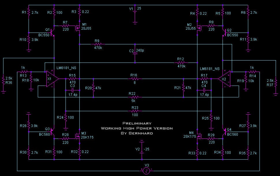
This is my working amp, with two 2.5kohm resistors added to make the currents trough the 0.22ohm Rs symmetric.
Also added the 17.4pF Cs to make the amp stable, and last but not least the 240pF C to get a nice square @ 100kHz.
It may be possible to connect the op amp outputs to ground and leave out the parts that are now connected to the op amp outputs.
But will the amp remain stable ?
In the end the madness circuit gives the same current waveform like the normal version, so I will forget about it.
It was a try and not for nothing because I learned a lot...
Also added the 17.4pF Cs to make the amp stable, and last but not least the 240pF C to get a nice square @ 100kHz.
It may be possible to connect the op amp outputs to ground and leave out the parts that are now connected to the op amp outputs.
But will the amp remain stable ?
An externally hosted image should be here but it was not working when we last tested it.
In the end the madness circuit gives the same current waveform like the normal version, so I will forget about it.
It was a try and not for nothing because I learned a lot...
Hi, Bernhard
The wiring of R36 and R37 are different. I assume R36 is correct. I would say: time to heat the iron!
/Hugo 😉
The wiring of R36 and R37 are different. I assume R36 is correct. I would say: time to heat the iron!
/Hugo 😉
Netlist said:The wiring of R36 and R37 are different.
I assume R36 is correct.
I would say: time to heat the iron!
Netlist,
yes, I redraw the schematic without testing afterwards
The other possibility that is left over is to make it classA pushpull and switch the bias via relais in 6 or 10 steps.
I am waiting for the rest of the LM6181 which I have ordered...
What Opamps would people suggest for a preamp?
Hi, fellas.
Just wondering... I have long toyed with the idea of using the X circuit to build some low power microphone preamps with say 50-70dB of gain. The space saving considerations of the monolithic approach is appealing, but I don't really know my opamps.
Can someone give me ideas where I can read up on the best ones for such an application?
I thought of getting something like the OpAmp Cookbook, any comments?
Better yet, does anyone have a favorite current feedback opamp for preamp level projects?
Thanks.
-Erik.
Re: What Opamps would people suggest for a preamp?
And please, call me Hugo...
Hi, Erik
The LM6181 is a very nice CF-opamp. We were able to make a lot of different circuits in this thread. Maybe someone will dig up a better one for what you want, but I say: give it a try!!
/Hugo
Cool, this black layout. If you still can live with the theory, go ahead; I wouldn't be able to leave my hands off the iron. 😉Bernhard said:
yes, I redraw the schematic without testing afterwards
And please, call me Hugo...
e.lectronick said:
Better yet, does anyone have a favorite current feedback opamp for preamp level projects?
Thanks.
-Erik.
Hi, Erik
The LM6181 is a very nice CF-opamp. We were able to make a lot of different circuits in this thread. Maybe someone will dig up a better one for what you want, but I say: give it a try!!
/Hugo
- Status
- Not open for further replies.
- Home
- Amplifiers
- Pass Labs
- Monolithic SuperSymmetry with Current Feedback