LM6181 -Thanks
Thanks, Hugo.
I appreciate the help. BTW, isn't the LM6181 the same opamp Nelson had in mind when he was drawing up plans for this monolithic project?
I didn't know that particular part would also be suited for low power applications (eg not driving speakers).
I just downloaded the spec sheet for it, I'll look it over.
While I've got your attention, is there a "standard" reference book for ic opamps that everyone uses?
Thanks,
-Erik.
Re: Re: What Opamps would people suggest for a preamp?
Hugo, 😀
in ClassA with 50W dissipation it gives 4W output, with 100W dissipation 20W, and with 200W dissipation 90W.
For a 20W amp, 15V rails would give less dissipation
Question is, if the LM6181 works in ClassA

P.S.
I am still thinking about the dynamic idle madness...
Problem is, that the idle modulation should come from a common device and not from 2 independent rails ? 😕
Otherwise it would kill the classA effect
Also I found, the voltage amp leaves classA and thus needs to be modificated.
And what about monolithic Aleph-X ?
Netlist said:If you still can live with the theory, go ahead;
I wouldn't be able to leave my hands off the iron. 😉
And please, call me Hugo...
Hugo, 😀
in ClassA with 50W dissipation it gives 4W output, with 100W dissipation 20W, and with 200W dissipation 90W.
For a 20W amp, 15V rails would give less dissipation
Question is, if the LM6181 works in ClassA
P.S.
I am still thinking about the dynamic idle madness...
Problem is, that the idle modulation should come from a common device and not from 2 independent rails ? 😕
Otherwise it would kill the classA effect
Also I found, the voltage amp leaves classA
and thus needs to be modificated.And what about monolithic Aleph-X ?
Re: LM6181 -Thanks
http://opamp.com/cf/browse.cfm?Main=ELECTRONICS/COMMUNICATIONS&Sub1=OPAMPS
is a small sample of what exists. For a more detailed or in-dept answer you will have to call the engineers of DiyAudio.
Maybe a search on this forum reveals more?
/Hugo 😉
e.lectronick said:is there a "standard" reference book for ic opamps that everyone uses?
Thanks,
-Erik.
Originally posted by jh6you
Is LM6181 (http://www.national.com/ds/LM/LM6181.pdf) suitable?J
Nelson answers:
Absolutely, in fact this is the part # I was looking at when
I wrote it up. I recall that there is also a dual part made
by National which might be even more convenient, but I
can't find it now. In any case, any "current feedback" op
amp will probably do the job.
http://opamp.com/cf/browse.cfm?Main=ELECTRONICS/COMMUNICATIONS&Sub1=OPAMPS
is a small sample of what exists. For a more detailed or in-dept answer you will have to call the engineers of DiyAudio.
Maybe a search on this forum reveals more?
/Hugo 😉
Bernhard said:
Question is, if the LM6181 works in ClassA.
If I look into the simplified schematic of LM6181, it seems to ever work in Class B. I mean LM6181 itself.
JH
jh6you said:
If I look into the simplified schematic of LM6181, it seems to ever work in Class B. I mean LM6181 itself.
JH
How do you see that ?
The output stage seems a bit complicated to me.
But I remember the 5kohm trick to force op amps into classA.
So maybe all of them are classB originally
well, I wouldn't get too worried
if its B or AB or A. All three can sound perfectly acceptable - especially once one remembers that the schematics that are shown in the datasheets are models, not true representations. Those little pieces of silicon are laser trimmed to close to perfection, moreso than you and I could ever match in a zillion years..
(Heresy I know, but the Saw Inquiry - if you gave a million monkeys an soldering iron, would you eventually get a Zen?)
Well, I'm not worried too much...
...because a 3.3 kohm from negative rail to output does the job.
Nice side effect: Now a classA output stage can be driven by the rails, which simplifies the circuit.
And...
...because a 3.3 kohm from negative rail to output does the job.
Nice side effect: Now a classA output stage can be driven by the rails, which simplifies the circuit.
And...
Single ended ?
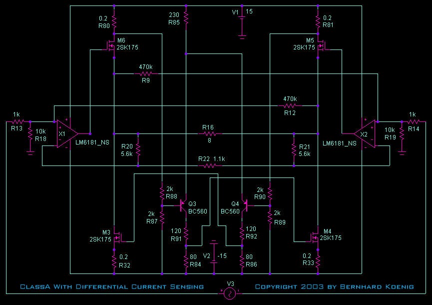
When adding the classA-trick resistors to the op amps, driving the fets by the op amp rail currents and playing a little with values,
the whole thing becomes single ended.
The currents through the lower op amp rails and the lower 0.22 ohm resistors are constant even @ full signal.
So the lower fets and the negative op rails act like constant current sources and the high side swings the signal
And this leads to madness again, until now I always tried to modulate the idle of a push pull, maybe with single ended and modulating the current source it is easier/better/aleph ?
But I don't like electrolytics...
Breaking News
I got 2 more versions working on the sim.
- basic circuit as built by JH and Netlist but with N-fets only 😀
- same but output stage single ended. 😀 😀
Slowly but surely I loose survey over all that versions...
I got 2 more versions working on the sim.
- basic circuit as built by JH and Netlist but with N-fets only 😀
- same but output stage single ended. 😀 😀
Slowly but surely I loose survey over all that versions...


I don't know if it is a problem that the currentvalues for the current sources are sensed from the other side.
If so, it should be possible to fix it.
The circuit swings 40Vpp.
I have also the high power version of this one ready, which swings to 72Vpp.
The degree of current modulation can be adjusted by values.
Very nice, however you want to realize that the modulation
for the current sources is dependent on the output voltage,
not the output current, thus it is idealized for a particular
resistive load value, and will not work as well for other values
or reactive components. This is why the Aleph current source
was designed around output current - to make it more load
independent.
Nelson Pass said:Very nice, however you want to realize that the modulation
for the current sources is dependent on the output voltage,
not the output current, thus it is idealized for a particular
resistive load value, and will not work as well for other values
or reactive components. This is why the Aleph current source
was designed around output current - to make it more load
independent.
The resistor network can also be connected to the op amp output, instead to the amp output.
I have more variations in progress.
Bernhard
Whilst sitting bored in a conference on auditing I was working on today, a thought came to mind about your "madness" amp.
Would it be more feasable, rather than changing the bias, to change the rail voltage level via a sort of bodged on cheap and cheerful B class amp?
Whilst sitting bored in a conference on auditing I was working on today, a thought came to mind about your "madness" amp.
Would it be more feasable, rather than changing the bias, to change the rail voltage level via a sort of bodged on cheap and cheerful B class amp?
pinkmouse said:
Would it be more feasable, rather than changing the bias, to change the rail voltage level via a sort of bodged on cheap and cheerful B class amp?
pinkmouse,
my madness amp behaves exactly like the basic circuit, so it is useless.
The madness idea led me to the above circuit that is single ended with dynamic current source, function is very similar with Aleph(X).
It saves 50% of wasted idle current in normal single ended classA.
The bad news for me is that with my 8 channels it is still far too much heat.
bodged 😕
If the rail voltage is reduced by whatever, the idle drops in that whatever and the heat goes in that whatever too 🙁
What could help is switching transformers or using swithcing psu.

daily madness
High power version of the
single ended classA dynamic current source monolithic super symmetry amp

But 200W idle x8 = 1600W is just too much for me
High power version of the
single ended classA dynamic current source monolithic super symmetry amp
But 200W idle x8 = 1600W is just too much for me
Re: daily madness
I remember how cold winters get in Germany, perhaps you could save it for use then😉
Well done though, keep, 'em coming Bernhard!
Bernhard said:But 200W idle x8 = 1600W is just too much for me
I remember how cold winters get in Germany, perhaps you could save it for use then😉
Well done though, keep, 'em coming Bernhard!
Hi Bernhard
Your research activities are really impressive.
I wish you will soon get successful findings.
JH
Your research activities are really impressive.
I wish you will soon get successful findings.
JH
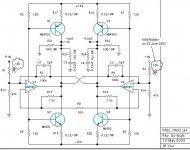
Updating:
I have tried to lower the value of the input resistors, R1 and R3, mainly to earn more signal gain. I have reduced the value from 20k to 10k. The 10k gives me a signal gain of 17dB, offers 40V peak-to-peak output, provides a better current supply to the current boosters and shows square waves staying in the best range of stable forms. I have found that if I go further down, e.g. less than 10k, the square waves start turning worse. Therefore, the 10k is set as a minimum value.
This is to make myself possible to look for a set of low dB speakers. I am thinking to buy ATC A7 (8 ohm 84dB) or Audio Physic Yara (4 ohm 90 dB). I consider that one of these two could give me a happy near-field listening during my 3-year stay in Shanghai.
JH
Attachments
- Status
- Not open for further replies.
- Home
- Amplifiers
- Pass Labs
- Monolithic SuperSymmetry with Current Feedback