Looking 12HL7 tubes, I found the brand Zenith, have any relation with Sylvania?
Zenith did not make their own tubes. They could be made by any of the major manufacturers. It is not uncommon to find several different manufacturers for the same type number. Most of the Zenith branded tubes that I have seen were made by GE.
Someone could point me a part of Mouser or Digikey,
I am at work now ant my populated board is at home, but I used the same long strip of .025 inch square, .100 spacing, pin headder for all the jumpers. Some are cut for 2 pins, some are 3 pins, while JP2 and JP7 are cut for 4 pins. The jumper plugs from an old computer board are used on all of the JP's.
I am considering a build using $1 13GB5's as output tubes
So am I. I got 10 of these, and I am planning to see just what their limits are🙂. Once I get the voltage and load requirements for a reasonably conservative build (1/2 to 3/4 of the melting point) is I will just use an Antek toroid with the two heater windings in series. I am thinking that a higher B+ like 450 volts or so and a 3300 ohm load will be my starting point. I choose that load because I have a large quantity of suitable OPT's. Sweep tubes can eat lots of plate voltage, it's the screen that you must respect.
I have been using these industrial control transformers for some time, but I have never seen one like that. Most have two identical windings on each side that can be seriesed, paralleled, or used individually.
Hi wicked1, I still have no the boards, I'm waiting to have more information but seems not to have much interest.
For now I'm gather the parts, I have all the tubes 6J4WA, OA2WA, 12HL7, 5AR4, and the cheap 6P3S-e to start, if nothing blows up, buy something from KT88.
One more question, I was looking at the site EDCOR, was thinking about the CXPP50-8-5K for the OPT but I have doubt about the PT, the XPWR002 would work? a center tap is necessary in the heater winding? it that will not work, one could tell me that would be appropriate? I would like a B+ about 420-440V, transformers are expensive and I prefer ask before wrong.
Tubelab.com, thanks for the reply, I wanted to know the brand Zenith was reliable and I see if it is.
If you have the tubes, post a picture showing the type number and maybe we can figure out who made them. GE tubes will usually have the number etched into the glass with some dots etched below the number. Sylvanias usually have the letters USA right below the number. RCA's have the number enclosed in an octagon.
Buy a dozen of 12HL7 , all brand Sylvania, do not buy any Zenith because they do not know the brand, but were identical to Sylvania, now I know they are legit and I can buy, thanks.
I forgot to mention, in relation to the question of the PT, I'm thinking of building monoblocks.
Advantages and disadvantajes?
Advantages and disadvantajes?
Something has been missing from my life.......I have been busy with life's little things like going to work to pay the bills....and even some fun things like going to Seattle to see my grandkids.....but there has been no glow, no smoke, damn, the soldering iron hasn't been turned on in....I don't even remember.
Somehow I managed to get this week off of work. We still have "stuff" scattered all over the house since cleaning out the warehouse. The plan was to spend the week sorting and organizing some of the "stuff" and listing some of it on Ebay, but my ADHD took control of my brain and then it happened......
I just needed to see some glow....even if I just connected some junk tubes up to a power supply and fried the life out of them.....it had to be done. Before I could connect the clip leads up to the power supply.....zap ADHD had planted another thought.
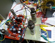
Last February I built two of these boards. I lit one of them up and extracted about 10 watts out of it WITHOUT any output tubes. That was post #36.....the board has been sitting on a shelf ever since. Well, I have a working driver board, a bunch of power supplies, some turret boards for several flavors of tubes, and lots of tubes, so maybe it's time to turn on that soldering iron......
Damn, it doesn't work. That's right, Tubelab doesn't even have a working soldering iron, NOOOOOOOO. I know there is another one here somewhere.....but where. I spent about an hour looking for it last night, then another hour this morning, so time for a brain shock......I jump in the cold swimming pool!!!!! 5 minutes later I am opening a box that contains a brand new soldering iron I bought a couple of years ago because the tip was stuck in my 15 year old iron.
OK, I have an iron, boards, power supplies, tubes, and all the other stuff I need.....Now, which tubes do I FRY.....no I mean "test". I have a credit at two tube stores since I have been selling off my tube collection, so how about one that is on the dollar menu......Then I remembered this:
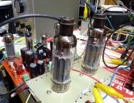
Well, I got 10 of them, they are on the dollar menu, so easy choice.....hook em up.....light em up.....Damn these little tubes CRANK!......Like how much power does it take to make these things GLOW.......50 watts......no too easy.....do I hear 100......NO GLOW YET.....CRANKKKKK.... a pair of these little guys can crank out 150 WATTS and just begin to show glow. Thats 150 W RMS at 3% distortion! Full cranked square waves read 190 Watts on the HP8903, but that's not really accurate.
I stopped twisting the dial at 600 volts because the last time I dimed the power supply into one of Pete's red boards there was a rather BIG BANG and a capacitor vanished. I don't remember exactly what voltage caps are in this board.....
So the details.....Load impedance is 3300 ohms. I am running a 6600 ohm OPT with a big fat 8.02 ohm Dale 120 watt resistor across the 16 ohm tap. Same setup I use with the big sweep tubes in Pete's big red board. The bias was adjusted for 35 mA per tube, and the screen voltage was set to 175 volts. I tested the setup at plate voltages from 300 volts to 600 volts. The same B+ supply was fed to the driver board and the output tubes. A second supply runs the output screens at 175 volts, and a third provides -80 volts to the red board.
I set the B+, set the bias to 35mA and cranked the signal generator until the audio analyzer read 3% THD, and pressed the power output button.
300 Volts 30 Watts
350 Volts 56 Watts
400 Volts 72 Watts
450 Volts 91 Watts
500 Volts 106 Watts
550 Volts 125 Watts
600 Volts 152 Watts
Don't know how they will work at 1200 ohms, but I suspect that's too low. I was surprised to see thay they liked 3300, most tubes this size don't like much below 5000. I have a way to do 2500 and 1250 ohms, but it involves finding an OPT that I haven't seen in at least a year.
I have some BIGGER tubes to test that might like the lower load, so I'll look for it.
Somehow I managed to get this week off of work. We still have "stuff" scattered all over the house since cleaning out the warehouse. The plan was to spend the week sorting and organizing some of the "stuff" and listing some of it on Ebay, but my ADHD took control of my brain and then it happened......
I just needed to see some glow....even if I just connected some junk tubes up to a power supply and fried the life out of them.....it had to be done. Before I could connect the clip leads up to the power supply.....zap ADHD had planted another thought.
Last February I built two of these boards. I lit one of them up and extracted about 10 watts out of it WITHOUT any output tubes. That was post #36.....the board has been sitting on a shelf ever since. Well, I have a working driver board, a bunch of power supplies, some turret boards for several flavors of tubes, and lots of tubes, so maybe it's time to turn on that soldering iron......
Damn, it doesn't work. That's right, Tubelab doesn't even have a working soldering iron, NOOOOOOOO. I know there is another one here somewhere.....but where. I spent about an hour looking for it last night, then another hour this morning, so time for a brain shock......I jump in the cold swimming pool!!!!! 5 minutes later I am opening a box that contains a brand new soldering iron I bought a couple of years ago because the tip was stuck in my 15 year old iron.
OK, I have an iron, boards, power supplies, tubes, and all the other stuff I need.....Now, which tubes do I FRY.....no I mean "test". I have a credit at two tube stores since I have been selling off my tube collection, so how about one that is on the dollar menu......Then I remembered this:
I am considering a build using $1 13GB5's as output tubes and a 1200 ohm plate to plate impedance output transformer
Well, I got 10 of them, they are on the dollar menu, so easy choice.....hook em up.....light em up.....Damn these little tubes CRANK!......Like how much power does it take to make these things GLOW.......50 watts......no too easy.....do I hear 100......NO GLOW YET.....CRANKKKKK.... a pair of these little guys can crank out 150 WATTS and just begin to show glow. Thats 150 W RMS at 3% distortion! Full cranked square waves read 190 Watts on the HP8903, but that's not really accurate.
I stopped twisting the dial at 600 volts because the last time I dimed the power supply into one of Pete's red boards there was a rather BIG BANG and a capacitor vanished. I don't remember exactly what voltage caps are in this board.....
So the details.....Load impedance is 3300 ohms. I am running a 6600 ohm OPT with a big fat 8.02 ohm Dale 120 watt resistor across the 16 ohm tap. Same setup I use with the big sweep tubes in Pete's big red board. The bias was adjusted for 35 mA per tube, and the screen voltage was set to 175 volts. I tested the setup at plate voltages from 300 volts to 600 volts. The same B+ supply was fed to the driver board and the output tubes. A second supply runs the output screens at 175 volts, and a third provides -80 volts to the red board.
I set the B+, set the bias to 35mA and cranked the signal generator until the audio analyzer read 3% THD, and pressed the power output button.
300 Volts 30 Watts
350 Volts 56 Watts
400 Volts 72 Watts
450 Volts 91 Watts
500 Volts 106 Watts
550 Volts 125 Watts
600 Volts 152 Watts
Don't know how they will work at 1200 ohms, but I suspect that's too low. I was surprised to see thay they liked 3300, most tubes this size don't like much below 5000. I have a way to do 2500 and 1250 ohms, but it involves finding an OPT that I haven't seen in at least a year.
I have some BIGGER tubes to test that might like the lower load, so I'll look for it.
Attachments
Last edited:
way to go George.......that's was awesome as always......the 13GB5 looks a lot like the PL504 although filament is 27 volts....expect those tubes to disappear soon...
the 13GB5 looks a lot like the PL504
There is a 27 volt version, the 27GB5. I have two, but they are Japanese, and very well used.....abused. The 27GB5 is a PL500 which is listed as a substitute for a PL504. Maybe a similar tube.
I have a way to do 2500 and 1250 ohms, but it involves finding an OPT that I haven't seen in at least a year.
Kinda hard for a pair of 400 watt OPT's to hide. They have been found, hookup tomorrow......maybe.
Like how much power does it take to make these things GLOW.......50 watts......no too easy.....do I hear 100......NO GLOW YET.....CRANKKKKK.....
Hilarious stuff, keep it up.
looking at the plate structures i am not really surprised....mind you the combined plate and screen is 22 watts...
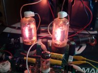
The 13GB5's cost me $1 each.....I was nice to those. I bought a BIG box full of 6BQ6GA's a few years ago for an average cost of about 35 cents each. This was the ugliest pair in the box, I CRANKED them a wee bit too far!
I figure that they were dissipating about 25 to 27 watts each at full crank. Most of that was plate dissipation. The screen current drops as you increase the plate voltage. Things didn't start heating up until I went past 500 volts.
mind you the combined plate and screen is 22 watts...
I figure that they were dissipating about 25 to 27 watts each at full crank. Most of that was plate dissipation. The screen current drops as you increase the plate voltage. Things didn't start heating up until I went past 500 volts.
Attachments
Last edited:
EL504/6GB5 and PL504/27GB5 are quite common down here (NZ), looks like there might be a use for them after all! Old Philips (Holland) manual suggests they are a higher power version (22.5 watts max PD vs 17) of EL/PL500, assorted Euro and Japanese ones I have here look pretty much the same. The 13 volt heater versions I have not seen though.
Kinda hard for a pair of 400 watt OPT's to hide. They have been found, hookup tomorrow......maybe.
...it will be interesting to see how low the B+ needs to be for these NOT to blow up with 1250 ohms load...
Hi, send an email to EDCOR to know the value of designing a transformer for my, $40 plus the value of the transformer.
Someone could help with specifications, please.
750V (375-0-375) at ¿400 mA? center tapped.
6.3V at ¿10A?
5V at 3A.
Would use 5AR4 or 5U4 and KT88.
Separate winding for the bias, how many mA? or integrated into secondary?
And that I will pay , I would like the best configuration.
Seems that design does not attract the attention of many people and Pete seems to be very busy at the moment, but for me it is perfect for learning an testing, I do not want an amplifier completed by the time, if finally not build these boards I use these transformer for a SSE, and would run hard a pair of KT90.
Thanks.
Your transformer design looks OK. The bias winding should be a seperate winding that is isolated from the other secondaries. I measure about 40 mA DC on the external power supply that I am using on my board. If you are going to run two boards it should be a 100 mA winding.
I hooked up the big Plitron OPT and tested with 1250 ohms and 2500 ohms. I was surprised to see excelent results at 2500 ohms, but the tubes aren't too happy with a 1250 ohm load.
The distortion at low power (about 5 watts) was about 2% in yesterdays testing at 3300 ohms. I made no attempt to reduce this, or even figure out why. I just turned up the idle current until the crossover notch went away, then increased it until the distortion stopped decreasing, the result was about 35 mA.
Today I removed the guitar amp OPT and connected up the big Plitron set for 2500 ohms. No other changes. The baseline distortion was 1.1%. OK, it IS a much better OPT. The power readings are at the point where the distortion increased to 3%. The data:
300 Volts 56 Watts
350 Volts 76 Watts
400 Volts 98 Watts
450 Volts 121 Watts
500 Volts 136 Watts ..... pale glow in a dark room
Then I changed the secondary tap to reflect 1250 ohms. These OPT's ARE rated for 1250 ohms at 400 watts. The baseline distortion was over 3%. Increasing the idle current to 45 mA brought it down to 2.1% so I left it at 45 mA. The data:
300 Volts 41 Watts
350 Volts 54 Watts
400 Volts 67 Watts
450 Volts 75 Watts ..... big red glow in a brightly lit room
Since the distortion started out at 2.1% it doesn't take much to hit 3%. More bias current didn't help much. I have been using output tube plate to driver tube plate feedback in all tests. Same concept as in the big red board. The resistor was arbitrarilly set at 141K ohms (3 X 47K in series). I did not try a different value.
...it will be interesting to see how low the B+ needs to be for these NOT to blow up with 1250 ohms load...
I hooked up the big Plitron OPT and tested with 1250 ohms and 2500 ohms. I was surprised to see excelent results at 2500 ohms, but the tubes aren't too happy with a 1250 ohm load.
The distortion at low power (about 5 watts) was about 2% in yesterdays testing at 3300 ohms. I made no attempt to reduce this, or even figure out why. I just turned up the idle current until the crossover notch went away, then increased it until the distortion stopped decreasing, the result was about 35 mA.
Today I removed the guitar amp OPT and connected up the big Plitron set for 2500 ohms. No other changes. The baseline distortion was 1.1%. OK, it IS a much better OPT. The power readings are at the point where the distortion increased to 3%. The data:
300 Volts 56 Watts
350 Volts 76 Watts
400 Volts 98 Watts
450 Volts 121 Watts
500 Volts 136 Watts ..... pale glow in a dark room
Then I changed the secondary tap to reflect 1250 ohms. These OPT's ARE rated for 1250 ohms at 400 watts. The baseline distortion was over 3%. Increasing the idle current to 45 mA brought it down to 2.1% so I left it at 45 mA. The data:
300 Volts 41 Watts
350 Volts 54 Watts
400 Volts 67 Watts
450 Volts 75 Watts ..... big red glow in a brightly lit room
Since the distortion started out at 2.1% it doesn't take much to hit 3%. More bias current didn't help much. I have been using output tube plate to driver tube plate feedback in all tests. Same concept as in the big red board. The resistor was arbitrarilly set at 141K ohms (3 X 47K in series). I did not try a different value.
Excellent work, George! How would you suspect the data would change if you lowered the screen volts on the 1250 ohm test? All tests were at 175 V, correct?
Care to hook up the 13GB5's as triodes?
Care to hook up the 13GB5's as triodes?
How would you suspect the data would change if you lowered the screen volts on the 1250 ohm test?
There's only one real way to find out, and it only involves turning a knob.......Turning the knob down makes things much worse, so.....I turned it the other way. With the plate voltage at 350, the screen at 200 and one of the feedback resistors jumpered so the total value is 94K (I am using 6HB6 drivers with a lowish plate resistance) there are now signs of life. baseline distortion is 1.4% and cranking the drive until I see 3% results in 94 WATTS, which coincides with the onset of pale glow in a dark room.
Care to hook up the 13GB5's as triodes?
You really want me to blow these guys up don't you. My previous experiences with sweep tubes in triode usually resulted in dead tubes...except for the 6AV5's. Oh, well I got 150 more of them on the way!
George, thanks for the prompt reply.
A winding with 60V at 100mA, would be sufficient to reach the 70V of negative voltaje which mentions Pete?, if no so, which voltaje would you suggest?
A center tapped would be advisable in the winding heaters, or is unnecessary?
BTW, how it sounds this driver?
A winding with 60V at 100mA, would be sufficient to reach the 70V of negative voltaje which mentions Pete?, if no so, which voltaje would you suggest?
A center tapped would be advisable in the winding heaters, or is unnecessary?
BTW, how it sounds this driver?
The data in the previous post at 94 watts at 3%, that is with 350 v B+, 200 v screen and 1250 ohm p-p output, correct?
Reducing the feedback resistance to 94k increases or decreases feedback with this arrangement?
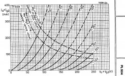
However, this is one of the few sweep tubes I have seen with triode curves, hopefully this will further the cause...
Reducing the feedback resistance to 94k increases or decreases feedback with this arrangement?
However, this is one of the few sweep tubes I have seen with triode curves, hopefully this will further the cause...
Attachments
- Status
- Not open for further replies.
- Home
- Amplifiers
- Tubes / Valves
- Mono push-pull driver PCB