There is only one heatsink. The heatsink is 6.47" tall which is the same internal height of the case so I milled a channel in the top center of the heatsink to run the power86 output wires. I ran the IEC leads around the right side of the heatsink to keep them away from the power86 output leads. And there is a slight hiss in the right speaker. The left speaker is dead quite. So should I run the IEC leads in some sheilding?
Shielding is not likely to be effective. But if you do go that route, use some shielded mains cable rather than cobbling something together yourself. Belden makes shielded mains cable.
I would still chop the ground wire for the ISS.
The cheapest mod will be to reroute the mains wiring so it goes through the channel in the heat sink. Just insulate it with plenty of heat shrink like you did for the other wires.
Tom
I would still chop the ground wire for the ISS.
The cheapest mod will be to reroute the mains wiring so it goes through the channel in the heat sink. Just insulate it with plenty of heat shrink like you did for the other wires.
Tom
I removed the ISS ground and the hiss is still in the right channel. Before I move the IEC leads to the channel, would the IEC leads very close to the power86 output leads be a concern? I always thought AC leads should not run close to and parallel to speaker wires and thought the same would apply to the output leads. Is that not true?
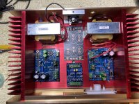
The chassis is almost tall enough to mount boards vertically.How tall is the chassis? One option could be to mount the MOD86 boards vertically and secure them with long standoffs to the rear (or front) panel.
Of the options you present I prefer Option 2, though I would consider mounting the rectifier on the bottom panel between the transformers. Then run the mains wiring straight up the middle of the chassis. Here's my rationale:
Option 1 doesn't allow you to get the wires into the terminal blocks. No bueno!
Option 3 runs the wires for the rectifier (nasty pulse currents) right over the input circuit for the left channel. That'll give hum.
Option 2 does have the (EI core!) transformer right by the input circuit on the right channel, but given the choice between having some stray electromagnetic field from the transformer engage with the input circuit (Option 2) and having the EM field from the rectifier currents do so (Option 3) I think Option 2 has the lower chance of inducing hum. That said, the right channel in Option 2 will measure worse that the left because of the coupling from the transformer. Sorry. Physics... 🙂
Placing the rectifier between the transformers in Option 2 and rotating the PSU board such that the wiring to the rectifier is as short as possible will limit the loop area in the rectifier harness, thereby minimizing its coupling into the rest of the circuitry. Keep the wires short and bundle them together with zip ties.
Tom
Option 1 could work as I reversed the directions of the terminal strips so the wires come in from the board side.
Option 4 (below) is what I will use. A couple little notches filed in the heat sinks allows the transformers to slide under the heat sinks for cap board clearance. Mount the cap board so the rectifier is at the rear. My inputs will be above it but there will be a couple of inches.
Alternatively, I could put the transformers at the front with the rectifier all the way at the front.
The smallest board is a VU driver board that uses the speaker output to drive the meters. Having with this chassis with a knob and two meters my plan is to replace the two 10k sensitivity pots on the meter board for the large center control and have adjustable sensitivity uncalibrated dancing meters...
Obviously the LM3886 chips are not quite centered. I'm not sure where the sweet spot is to optimize heat sink utilization vs. getting the one channel input as far away from a transformer as possible.
Attachments
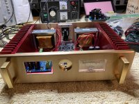
I used the previous boards where LM3886 wasn't centered, and realized too late the case I bought was cute, but really small. So I just mounted one board upside down to center the LM3886 on the heatsink. I used angle brackets to secure the boards to the heatsink.Obviously the LM3886 chips are not quite centered. I'm not sure where the sweet spot is to optimize heat sink utilization vs. getting the one channel input as far away from a transformer as possible.
I swapped the speaker connections so now the left XO/speaker is connected to the amp right channel and right XO/speaker is connected to amp left channel. I thought this might eliminate the speakers and XOs as the cause. The slight hiss moved to the left speaker and the right channel XO/speaker is now dead quite. Seems the hiss is coming from the amp right channel. What would be the next test to find the problem? I'm going to swap the preamp outputs to the amp. Maybe the preamp is the problem.I removed the ISS ground and the hiss is still in the right channel. Before I move the IEC leads to the channel, would the IEC leads very close to the power86 output leads be a concern? I always thought AC leads should not run close to and parallel to speaker wires and thought the same would apply to the output leads. Is that not true?
Last edited:
Seems it is the preamp. The hiss is typical when tubes start going bad.I swapped the speaker connections so now the left XO/speaker is connected to the amp right channel and right XO/speaker is connected to amp left channel. I thought this might eliminate the speakers and XOs as the cause. The slight hiss moved to the left speaker and the right channel XO/speaker is now dead quite. Seems the hiss is coming from the amp right channel. What would be the next test to find the problem? I'm going to swap the preamp outputs to the amp. Maybe the preamp is the problem.
No. The output of the Power-86 is very low impedance which makes it hard for any EM field coupled into them to induce any significant voltage.Before I move the IEC leads to the channel, would the IEC leads very close to the power86 output leads be a concern?
See above. The speaker output of a MOD86 is very low impedance.I always thought AC leads should not run close to and parallel to speaker wires and thought the same would apply to the output leads. Is that not true?
The input is high impedance, so AC wiring will have an easier time coupling into that. So keep the input wiring away from AC wiring (and the rectifier wiring) to the extent possible.
Tom
Maybe it is. If swapping the inputs to the power amp (or the outputs of the preamp - same thing) causes the hiss to move from one channel to the other, the hiss is coming from the preamp.I'm going to swap the preamp outputs to the amp. Maybe the preamp is the problem.
Tom
Nice layout except it forces the input wiring to run right over the transformer. I'd rotate it 180º, but that's me.Option 4 (below) is what I will use. A couple little notches filed in the heat sinks allows the transformers to slide under the heat sinks for cap board clearance. Mount the cap board so the rectifier is at the rear. My inputs will be above it but there will be a couple of inches.
You could also keep the layout as-is and run the inputs using StarQuad cable. That along with the differential input of the MOD86 will eliminate any hum induced on the wiring - assuming you have a source with a balanced/differential output.
Tom
Thanks Tom. In post 5927 I said... Seems it is the preamp. The hiss is typical when tubes start going bad. I'll be replacing tubes tonight.
New Philips PCC88 7dj8 tubes and beautiful, dead, silence.Thanks Tom. In post 5927 I said... Seems it is the preamp. The hiss is typical when tubes start going bad. I'll be replacing tubes tonight.
Intially I didn't belive it could be the preamp because I put NOS CV2493 KQDD/K tubes in the preamp two years ago and expected them to last for at least about five years. However, the Audible Illusions M3A is considered to be hard on tubes. I hope the Philips tubes last longer.New Philips PCC88 7dj8 tubes and beautiful, dead, silence.
Even though there is no hiss I bought two feet of Belden 8719 and will use that in my mod86 and parallel86.
Based on your recommendation to keep AC leads away from inputs I think the attached photo shows the AC leads are too close and parallel to the input wires and should be moved.No. The output of the Power-86 is very low impedance which makes it hard for any EM field coupled into them to induce any significant voltage.
See above. The speaker output of a MOD86 is very low impedance.
The input is high impedance, so AC wiring will have an easier time coupling into that. So keep the input wiring away from AC wiring (and the rectifier wiring) to the extent possible.
Tom
One saving grace is that you're using balanced inputs (and presumably a source with balanced output). The CMRR of the differential receiver in the Modulus-86 will attenuate any hum induced on the input wiring by 80+ dB. That said, the wires do run right over the input section of the Modulus-86 board.
The transformer primary carries the same nasty charging currents as the secondary, albeit reduced by the turns ratio of the transformer, so it's only the second-worst offender for EMI. I'd rate the secondary wiring (basically anything that connects to the rectifier) as the worst offender. This is why you want those wires tightly bundled (as you have them).
So you have a choice. On one hand your amp is assembled and performs well. You mentioned that you have no hum in the speakers - or at least no hum that can be attributed to the amp. So doing nothing is a perfectly valid option. Ain't broken. Don't fix. But on the other hand you could probably get measurably better performance if you moved the AC mains wiring so it runs down the middle of the chassis even if that puts it in close proximity (and parallel to) the power and output connections for the amp modules. If you choose this route, just make sure to protect the wires where they go through the milled channel in the heat sink.
Choices, choices... 🙂
Tom
Some argue that it does. I argue that with heavy gauge wire it's hard to get a tight twist so you're better off bundling the wires.
They key is that you want the wires to be tightly coupled. So you want them running side-by-side with as little gap in between as possible. If you can do that with a twist, great. If not use a bundle. I've always bundled and haven't had issues.
Totm
They key is that you want the wires to be tightly coupled. So you want them running side-by-side with as little gap in between as possible. If you can do that with a twist, great. If not use a bundle. I've always bundled and haven't had issues.
Totm
I just replaced the AC leads to the IEC with Belden 8719 shielded cable and would appreciate some guidance in grounding the drain wire. The photos show how I thought it could be connected to the same chassis grounding lug used for the IEC ground wire. The drain wire would be connected to the wire with the wire nut. Is this approriate?
Thanks


Thanks
- Home
- Amplifiers
- Chip Amps
- Modulus-86 build thread