changing power supplies
That would save me $$ in the Parallel86 build because I would move the Antek AS-3224 and Power-86 to the Paralle86 stereo amp and buy an SMPS-86 for my Mod86.
However if I change to more power hungry or lower impedance speakers I might regret that and maybe 120dBV is a smidge better than 110dBV.
What ever, I'm staying with the Power-86 in the Mod86.
After reading your post on the SMPS-86 I was considering buying one for my Mod86.Correct. The output power drops to 28 W (8 Ω), 42 W (4 Ω) with the SMPS-86 due to the lower output voltage.
With the SMPS-86, I measured 42 µV RMS (unweighted), 33 µV RMS (A-weighted) of output noise.
I looked briefly at the output mains hum. -110 dBV with the SMPS-86.
It does indeed look like the Modulus-86 really doesn't care what supply you use. The output power is lower due to the lower output voltage of the SMPS-86. This means the amp hits clipping at about 1.5 V RMS input. These are the only changes I foresee in the spec table when switching from the Power-86 to the SMPS-86.
Tom
That would save me $$ in the Parallel86 build because I would move the Antek AS-3224 and Power-86 to the Paralle86 stereo amp and buy an SMPS-86 for my Mod86.
However if I change to more power hungry or lower impedance speakers I might regret that and maybe 120dBV is a smidge better than 110dBV.
What ever, I'm staying with the Power-86 in the Mod86.
The sanding flat of the back of the IC and small area, where its rests, on the heatsink, along with a very light film of thermal grease, have worked great. The heatsink gets up to the occasional 90F but the chip always measures lower. Being new to building an amp, I'm inclined to think that that is a good indication that the IC heat is being soaked up by the heatsink. Is that how it should work or am I missing something?
The heatsink gets up to the occasional 90F but the chip always measures lower. Being new to building an amp, I'm inclined to think that that is a good indication that the IC heat is being soaked up by the heatsink. Is that how it should work or am I missing something?
The principles of heat transfer require that for heat to move from the IC to the heatsink the IC must be at a higher temperature than the heatsink.
All I know is what I've measured. I guess I assumed incorrectly that the heatsinks was really drawing the heat away from the IC, faster than the IC could produce it. Remember, I said I'm new to this. So why does the IC measure cooler than the heatsink? Something must be screwed up with my setup. I trust my temp. sensor and my finger tips.
Heat only flows from an object at a higher temperature to an object at a lower temperature...it's the most fundamental principle of thermodynamics. If the heatsink is at 90F it will transfer heat to ambient air at a lower temperature...typically in the 70s. The fact that the heatsink is above ambient temperature confirms that heat is being transferred to it presumably from the IC. That can only happen if the IC is at a higher temperature at the interface where the heat transfer occurs. I'm not sure why your measurements suggest otherwise but this is a facet of the second law of thermodynamics and is on as solid ground as any principle of physics.
You get 0 V on all four boards?
ummm,.. Well no actually, but I only discovered that a minute ago. I was measuring in the wrong place. I found pin 4, and I thought pin 8 was directly across, but actually it was pin 5 that I measured. Once I found the correct location of pin 8 things looked as they should plus AND minus 15. At least on the last one, I suspect the other three are fine too, but they are disconnected at the moment.
I did measure the toroid secondaries without the power86 attached. 22.5 if I recall, it looked in spec so I didn't write it down.
Then I disconnected the mod86 from the power86 and measured v+ and v-. Both looked good, 31.5 something I think.
My one concern, is when I had all 4 mod86 connected, I had a very dim glow on my lightbulb in series with mains. When I had one mod86 at a time connected the light was dead black (except of course for the initial flash of the caps charging)
Is it normal to see a little glow simply because of the multiple boards drawing more than one board alone?
Tom:
I suggest testing the amp block by block. Start with the power supply. Once you have ±30-32 V out with no load, connect the amps. With four amps connected, I'd expect around ±28-30 V out of the Power-86 at nominal mains voltage.
Tom[/QUOTE]
That was a good suggestion to go through block by block. I have yet to connect all four boards again, to remeasure vee and vcc, but I think the +/- 18 was an accurate measurement. I'm wondering if I should use an Avel 330VA 25+25 instead? I have one on the shelf. Or should I increase cap size in power86? I'm thinking the caps are good enough there won't be ripple, but I'm hoping I'll have enough power to get 40 watts from each board.
temp measurement
Maybe the IC is measuring lower than the heatsink because I'm measuring the IC temp on the front face and maybe that surface is cooler than the IC surface in contact with the heatsink.
Heat only flows from an object at a higher temperature to an object at a lower temperature...it's the most fundamental principle of thermodynamics. If the heatsink is at 90F it will transfer heat to ambient air at a lower temperature...typically in the 70s. The fact that the heatsink is above ambient temperature confirms that heat is being transferred to it presumably from the IC. That can only happen if the IC is at a higher temperature at the interface where the heat transfer occurs. I'm not sure why your measurements suggest otherwise but this is a facet of the second law of thermodynamics and is on as solid ground as any principle of physics.
Maybe the IC is measuring lower than the heatsink because I'm measuring the IC temp on the front face and maybe that surface is cooler than the IC surface in contact with the heatsink.
I think I'm all good here. I get 0.00 mV DC offset at speaker post within 7 seconds, input shorted to ground of course.
I have just a tad more soldering to do before I can install. I need to cut the RCA off the pseudo cables I made and install the XLR ends. The pseudo cables worked very well, I was able to build up the system over time, and able to enjoy the DAC-Preamp I made with Tom's THAT Line Driver boards last year.
Now I'll be able to take full advantage of that differential/balanced signal from source to amp.
Maybe the IC is measuring lower than the heatsink because I'm measuring the IC temp on the front face and maybe that surface is cooler than the IC surface in contact with the heatsink.
Yes, that is a very likely explanation as the material in the case of the IC would have much higher resistance to the flow of heat than the path through the back of the die to the heatsink.
I found pin 4, and I thought pin 8 was directly across, but actually it was pin 5 that I measured.
DOH!!
Once I found the correct location of pin 8 things looked as they should plus AND minus 15.
Cool.
Then I disconnected the mod86 from the power86 and measured v+ and v-. Both looked good, 31.5 something I think.
Sounds good so far.
My one concern, is when I had all 4 mod86 connected, I had a very dim glow on my lightbulb in series with mains. When I had one mod86 at a time connected the light was dead black (except of course for the initial flash of the caps charging)
Is it normal to see a little glow simply because of the multiple boards drawing more than one board alone?
Considering that I don't have any information on the bulb or what you consider "dim", I can't answer that. However, ***IF YOU CAN DO SO SAFELY***, you can insert an AC ammeter in series with the mains connection and measure the current drawn by the amp from the mains.
Considering that each MOD86 draws 55-60 mA typical and the turns ratio of the transformer is about 120:44, I'd expect 4*60*44/120 = 88 mA of current drawn from the mains.
I suspect the amp is working fine and the lightbulb tester is causing enough voltage drop on the primary of the transformer to cause the output voltage of the Power-86 to drop.
Are you able to safely measure the voltage going into the transformer? I'm guessing it'll be around 80 VAC due to the voltage drop across the bulb tester.
If the mains inlet to the amp is fused (and if you follow my design documentation, it should be), you can also take the lightbulb tester out and plug the amp directly into the mains. You should then see about ±30 V on the supply.
An intermediate step would be to use a higher wattage (lower resistance) bulb in the lightbulb tester. Try with a 100-150 W halogen bulb. You should see a higher output voltage on the Power-86.
There should be absolutely no need for you to change the power transformer. I use an Antek AS-3222 in my amp and am getting the ±30 V I mention.
Tom
Last edited:
You're a genius Tom. I didn't realize the lightbulb would limit so much.
Without the bulb I get +/-32.5V at the output of power86 board, with all four Mod86's connected. So that's good too.
Measuring AC Amps, I don't believe my multimeter does that. I have some large junction blocks so I could rig an apparatus to securely hold the wires and do it safely if I had the right meter. My multimeter has three poles to plug into, COM the black one always goes there, then Volt/Ohm/mA is the one I mostly use, the third one is labeled 10ADC (10A/250V Max),... So that's only for measuring Amps Direct Current, and I should not use it to measure Amps Altranatung Current, right?
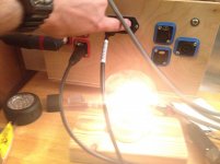
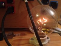
The bulb I have is 40 watts I think, and it is very dim, difficult for a photo to render a good likeness because the variable of exposure and brightness on your screen will make you wonder. I have two pics for comparison, one is the flash while the caps charge, we'll call this the reference photo, because you can imagine that's pretty bright like a reading lamp for just an instant, the second photo is the dim glow with amp at idle.
Honestly, because each board individually did not illuminate the test light at all, I'm feeling confident all is well anyway.
Well, back to wiring for me. I need to add SpeakOn connectors to my lxmini speakers now.
Without the bulb I get +/-32.5V at the output of power86 board, with all four Mod86's connected. So that's good too.
Measuring AC Amps, I don't believe my multimeter does that. I have some large junction blocks so I could rig an apparatus to securely hold the wires and do it safely if I had the right meter. My multimeter has three poles to plug into, COM the black one always goes there, then Volt/Ohm/mA is the one I mostly use, the third one is labeled 10ADC (10A/250V Max),... So that's only for measuring Amps Direct Current, and I should not use it to measure Amps Altranatung Current, right?
The bulb I have is 40 watts I think, and it is very dim, difficult for a photo to render a good likeness because the variable of exposure and brightness on your screen will make you wonder. I have two pics for comparison, one is the flash while the caps charge, we'll call this the reference photo, because you can imagine that's pretty bright like a reading lamp for just an instant, the second photo is the dim glow with amp at idle.
Honestly, because each board individually did not illuminate the test light at all, I'm feeling confident all is well anyway.
Well, back to wiring for me. I need to add SpeakOn connectors to my lxmini speakers now.
Attachments
You're a genius Tom. I didn't realize the lightbulb would limit so much.
Thanks. I do consider myself to be a bit brighter than the bulb shown in Post #2333. 🙂
Without the bulb I get +/-32.5V at the output of power86 board, with all four Mod86's connected. So that's good too.
Yep. If you also have 0 V DC on the output of the MOD86 amps, proceed with the following:
- Create a 5-second long 400 Hz test tone at -3 dBFS using wavtones.com.
- Connect your audio player to the amp and play the test tone on repeat.
- Turn up the volume until you get a good strong signal (say 100 mV RMS AC) on the input of the MOD86 (measure from pin 2 to pin 3 of the input connector).
- Measure the output voltage with your AC voltmeter. You should have Vout = 10*Vin, so 1.0 V RMS AC for 100 mV in.
Tom
It would be interesting to know the temp of the back of the IC. My measurements of the heatsink within 1/8" of the IC have not gone above 90F. That low heatsink temp makes me wonder if there is good transference from the back of the IC to the heatsink. Anyone have any thoughts on that?
One thought: Your amp is working fine and the heat transfers to the heat sink just fine. Please read Kevin's responses above regarding thermodynamics. There is no action for you to take. Leave it alone. Enjoy the music.
The reason the heat sink does not get scorching hot is that the amp doesn't dissipate that much power. Even if you really crank it, you may get up to 5-10 W of output power on average given your relatively inefficient speakers and large listening space. Under these circumstances the heat sinks should be lukewarm, so your 90 ºF sounds reasonable.
For more information, please see the Thermal Design part of my Taming the LM3886 Series.
I don't understand the idea that the heat sink must be scorching hot in order to work. You are missing the most important temperature measurement: The die temperature. As the LM3886 does not have a built-in calibrated temperature sensor, there is no way to determine the die temperature. An IR thermometer, such as the FLIR One may provide a guess.
Tom
Last edited:
...makes me wonder if there is good transference from the back of the IC to the heatsink. Anyone have any thoughts on that?
henryjr,
As Tom has suggested there is no reason for you to be concerned about the die temperature unless the LM3886 is going into protect mode. The fact that it isn't is all the evidence you need to assure yourself that the heat transfer interface between the die and heatsink is working just fine. I assume the reason you bought Tom's boards was to benefit from his expertise and superior engineering so that all you had to do was follow his guidelines and do a competent job of assembly. It appears you have held up your end of the bargain so just enjoy the music!
IC temp
Again I did poor job of writing my post. I'm not worried or concerned. I'm listening and enjoying the amp all the time. It was just a thought and maybe someone had experience measuring the back of the IC. Plan old curiosity.
I know everything is working properly because the sound is fantastic.
One thought: Your amp is working fine and the heat transfers to the heat sink just fine. Please read Kevin's responses above regarding thermodynamics. There is no action for you to take. Leave it alone. Enjoy the music.
The reason the heat sink does not get scorching hot is that the amp doesn't dissipate that much power. Even if you really crank it, you may get up to 5-10 W of output power on average given your relatively inefficient speakers and large listening space. Under these circumstances the heat sinks should be lukewarm, so your 90 ºF sounds reasonable.
For more information, please see the Thermal Design part of my Taming the LM3886 Series.
I don't understand the idea that the heat sink must be scorching hot in order to work. You are missing the most important temperature measurement: The die temperature. As the LM3886 does not have a built-in calibrated temperature sensor, there is no way to determine the die temperature. An IR thermometer, such as the FLIR One may provide a guess.
Tom
Again I did poor job of writing my post. I'm not worried or concerned. I'm listening and enjoying the amp all the time. It was just a thought and maybe someone had experience measuring the back of the IC. Plan old curiosity.
I know everything is working properly because the sound is fantastic.
Aye, quit messing before you break it.Anyone have any thoughts on that?
Aye, quit messing before you break it.
+1. If it ain't broken, don't fix it.
... or in the words of Red Green, "If it ain't broken, you ain't trying!" 🙂
Tom
- Home
- Amplifiers
- Chip Amps
- Modulus-86 build thread