Just use a T-handle tap wrench and easy to control by feel plus just reverse every turn to break the chips. Tap with a lubricant and methylated spirits works well when tapping aluminium.
That's my preferred method as well. I use a tapping block to keep the tap square. You can buy them ... or just make one by drilling holes into a square block of aluminum. The holes do need to be square though. That's the point of the block... 🙂
Good timing we are sharing tap smashing stories. I need to take deepbreath and start making swarf.
Nah... Why rush into these things? 😉
Tom
Or a cheap belt driven pillar drill, and drive the belt manually. I stopped messing up treads and breaking taps since I use that method. Much faster than T-handle too.That's definitely a drool-worthy setup.
You can get a chuck designed for tapping. I imagine it's expensive as it has a reduction gear inside, but that could be something to entertain if you cut a lot of threads.
Tom
Last edited:
Nah... Why rush into these things? 😉
Tom
Well Boy Child wasn't born when I finished soldering the boards and he starts school next week... I think I have procrastinated enough now!


I used to use lubrication. Peter Daniel recommended tap water. Tried it on a few heatsinks and still use it.
I used to use lubrication. Peter Daniel recommended tap water. Tried it on a few heatsinks and still use it.
Tap water causes tools to rust. Ethanol works as a lubricant with aluminum ... and doesn't cause rust.
Tom
Citrus oil for steel or aluminium, lubricates taps, drills and saws perfectly, also good cleanup solvent and smells pleasant.
Dan.
Dan.
Been listening to the Mod86's for a couple of weeks now and these are by far the best amps I have had. I suspect these will see me out.
Hey Tom,
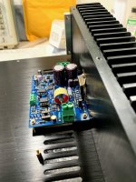
I've been working on the build for a while and finally got to power it up. One channel works fine and the DC offset goes to 0. The other channel on the other hand is not working properly. The DC offset is around 5V which is not good.
I checked and rechecked all the solder joints, the top and bottom of the board, compared everything between the working on non working channel making sure the capacitors, diodes and everything else are put on correctly and everything seems to check out so I'm at a loss as to what is going on.
on the non-working channel, the LM3886 gets real hot. Even R10 gets really hot, like blimey hot. D2 and D5 are measuring 12.5v and D3 and D4 are measuring 15.5V - 16V. Those are different than the working channel.
What do you think might be going on?
Kevin
Attachments
Tom is better able to help. Contact offline and he can give you a path of things to check.
I think it is a connection issue.
I think it is a connection issue.
Are the + & - rail voltages OK at J3. The fact that R10 is getting hot would indicate to me you may have a - voltage rail issue.
If the rail voltages are ok I would remove the THAT1200 and recheck the voltages. Also check D2-5
D2 and D4 go to INN and D3 and D5 to INP so I am not sure what you are measuring here.
If the rail voltages are ok I would remove the THAT1200 and recheck the voltages. Also check D2-5
D2 and D4 go to INN and D3 and D5 to INP so I am not sure what you are measuring here.
Last edited:
Been listening to the Mod86's for a couple of weeks now and these are by far the best amps I have had. I suspect these will see me out.
I'm glad to hear that you like the Modulus-86. It's a nice amp indeed.
Tom
I've been working on the build for a while and finally got to power it up. One channel works fine and the DC offset goes to 0. The other channel on the other hand is not working properly. The DC offset is around 5V which is not good.
I agree. 5 V offset is pathetic. Let's figure out what's going on. Gross errors like that are usually caused by a bad solder joint, accidental part swap, or by an IC pin that didn't make it into the socket. I've seen cases where the IC pin curled up under the IC and didn't get into the socket.
on the non-working channel, the LM3886 gets real hot. Even R10 gets really hot, like blimey hot.
Sounds like you have some oscillation going on. It looks like R1 has been damaged. At least the enamel has cracked and flaked off in one end. That could set the LM3886 up for oscillation, so I suggest replacing that.
D2 and D5 are measuring 12.5v and D3 and D4 are measuring 15.5V - 16V. Those are different than the working channel.
I'm not sure what you mean by that. Where are you measuring on those diodes?
To start, I'd measure the "±15 V" supply. You should have around ±15 - ±18 V on those supplies. You can find them on the OPA2277 (pin 4 should be about -16.5 V and pin 8 should be about +16.5 V). You will have some variation due to component tolerances and such, but the voltage should be within the ±15 to ±18 V range.
I'm happy to help, but suggest that we take the discussion offline. Just toss me an email (take my username here and add @neurochrome.com). Note that I'm out of the office until Friday so my response time will be a bit longer than normal.
Tom
Thanks everyone.
I checked the solder joints top and bottom and re-soldered many of them just in case and it's still running hot. I checked all the resistors and they seem to match the working board but i also noticed R1 looking chipped or something so I'll replace that. I'll also try pulling out the opamps and re-seating them and see if that works, check the voltages, etc/
If it doesn't, I'll shoot you an email Tom.
You can power up the board with all the opamps removed, actually. If that works, the error is somewhere in the small-signal portion of the board (i.e. among the opamps and associated components). With all the opamps removed, you should have below 100 mV of DC offset on the amp output.
Tom
Tom
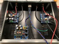
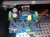
Okay, I got it up and running.
I followed Tom's instructions to pull out the op-amps and after doing that, the problem was gone. I then put them back in and removed them one by one to isolate which one it was. After figuring that out, I figured it had to something around the opamp. From the very beginning of the build, I told myself if I made any mistake, it would be that I put one of the blue capacitors in the wrong place. They are so tiny and hard to read and therefore would be the hardest to troubleshoot. I pulled out the magnifying glass and headlamp and started inspecting each one . C6 ended up being some random capacitor that didn't match anything else in the entire build. So I would like to think that Mouser just put the wrong one in the bag but the truth is that I probably made the mistake.
After replacing it, the amp fired up perfectly.
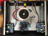
Too soon to say much about the amp other than it's dead quite and sounds super clean. I'll report back after giving it some good listening time.
I used the 2U Dissapante and had them cut the holes on the rear panel. I created the CAD design which was a first for me and I didn't screw it up so was happy about that. I went with the larger chassis in case I ever wanted to add more channels in the future.
I followed Tom's instructions to pull out the op-amps and after doing that, the problem was gone. I then put them back in and removed them one by one to isolate which one it was. After figuring that out, I figured it had to something around the opamp. From the very beginning of the build, I told myself if I made any mistake, it would be that I put one of the blue capacitors in the wrong place. They are so tiny and hard to read and therefore would be the hardest to troubleshoot. I pulled out the magnifying glass and headlamp and started inspecting each one . C6 ended up being some random capacitor that didn't match anything else in the entire build. So I would like to think that Mouser just put the wrong one in the bag but the truth is that I probably made the mistake.
After replacing it, the amp fired up perfectly.
Too soon to say much about the amp other than it's dead quite and sounds super clean. I'll report back after giving it some good listening time.
I used the 2U Dissapante and had them cut the holes on the rear panel. I created the CAD design which was a first for me and I didn't screw it up so was happy about that. I went with the larger chassis in case I ever wanted to add more channels in the future.
Attachments
- Home
- Amplifiers
- Chip Amps
- Modulus-86 build thread