I did a series of measurements of one of the tweeters before I changed the fluid, from -21db to 0db (where -6db was I think 2V) I did the same after. Didn't notice any power compression in either. I did both sets without moving any of the measurement gear. some minor differences in the FR before and after.
I had one tweeter that had a normal looking impedance plot and one with a wonky one. After changing the wonky one it looks normal, but the one that was normal now looks wonky 😀
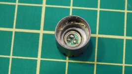
I had an Oh **** moment when I was thinking why are no drops of fluid coming out, and suddenly realized the gap was completely overly full. I was holding it too close to the gap and it was just flowing out! Luckily I bought a big tube (in case I stuffed up) as the price difference between 100uL and 600uL I think was only about $5. Wasted a heap on that first tweeter, had enough (I think) for the second one. the instructions I found online said two to three drops but no way that would be enough.
Anyway the subjective evaluation is that they are much less harsh now, but I may need to now modify the crossover....
Something was screwy with my impedance measurements, so not sure if I have a valid before and after... But I did a measurement with the crossover and it looked screwy, it was a quick and dirty in room though so will have to do proper measurements to find out if something really needs changing. Certainly sounds ok. Imaging seemed to be a bit better too.
I had one tweeter that had a normal looking impedance plot and one with a wonky one. After changing the wonky one it looks normal, but the one that was normal now looks wonky 😀
I had an Oh **** moment when I was thinking why are no drops of fluid coming out, and suddenly realized the gap was completely overly full. I was holding it too close to the gap and it was just flowing out! Luckily I bought a big tube (in case I stuffed up) as the price difference between 100uL and 600uL I think was only about $5. Wasted a heap on that first tweeter, had enough (I think) for the second one. the instructions I found online said two to three drops but no way that would be enough.
Anyway the subjective evaluation is that they are much less harsh now, but I may need to now modify the crossover....
Something was screwy with my impedance measurements, so not sure if I have a valid before and after... But I did a measurement with the crossover and it looked screwy, it was a quick and dirty in room though so will have to do proper measurements to find out if something really needs changing. Certainly sounds ok. Imaging seemed to be a bit better too.
Thanks for the update. It always seemed tricky to figure out how much fluid is required. Once the VC is installed it would be hard to tell how "full" the remaining gap is. Seems like it was worth doing for your speakers 🙂
I repaired a set of Mission tweeters that had broken VC's from an input "hot plugin" on a powered amp. Some of the fluid was blown into the back of the silk domes. I repaired it, cleaned it up, and it works but it's running a little short of fluid I suspect. I measured it but was never sure how much it changed (no baseline) and what caused it. They're also short 1 winding on the VC from the repair. Sufficient quality for workout music. 🙂
I repaired a set of Mission tweeters that had broken VC's from an input "hot plugin" on a powered amp. Some of the fluid was blown into the back of the silk domes. I repaired it, cleaned it up, and it works but it's running a little short of fluid I suspect. I measured it but was never sure how much it changed (no baseline) and what caused it. They're also short 1 winding on the VC from the repair. Sufficient quality for workout music. 🙂
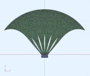
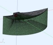
AKABAK sim : Radial Finned Horn + D2200Ph
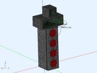
This horn model originated from off line collaboration with @docali and @fluid that initially started with Yuchi A290 radial finned horn models. It resulted in some interesting improvements and I was curious about how one of these horns would perform with my D2200Ph driver for my midrange.
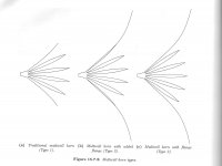
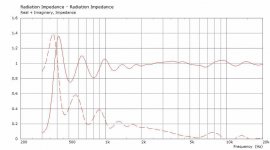
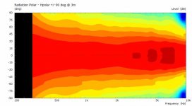
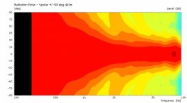
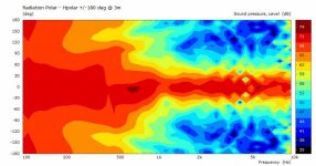
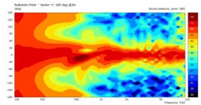
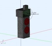
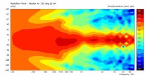
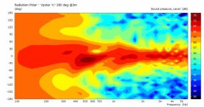
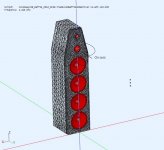
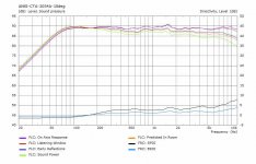
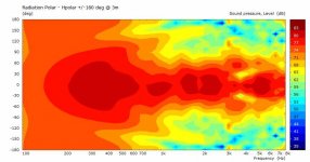
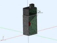
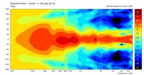
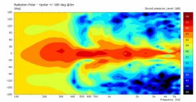
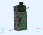
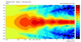
The fin arrangement (pic#3, type "c") was taken from High Quality Horn Loudspeaker Systems (Bjorn Kolbrek / Thomas Dunker) and the horn surfaces were calculated using @docali's calculator (spreadsheet) and surface reconstruction to STEP by @fluid. The RadImp (pic#4) and polars (pic#5,6) show the horn loads quit low and has relatively constant directivity.
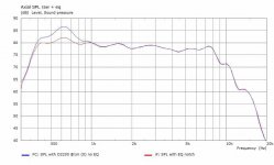
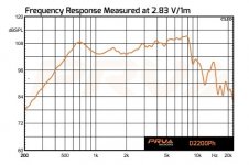
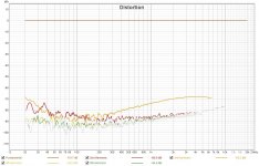
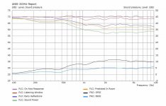
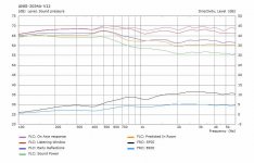
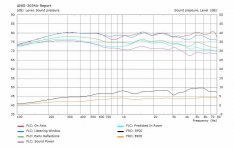
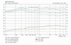
This sim uses the throat velocity profile taken from a D2200Ph PWT measurement (velocity curve in previous posts). This radial horn loads lower than the previous ZXPC horn, so now the D2200Ph bump (~600Hz) is visible (also shown with notch filter, pic#7) in the system axial SPL curve. The radial horn loads lower than the driver is capable of (it rolls off ~400Hz), and the driver also limits the HF performance (rolls off ~8KHz). PRV only provides test data for this driver on an exponential horn (pic#8, and I did ask them for PWT data). This system is easily capable of covering my midrange needs without excessive EQ as the system's axial SPL curve can be predicted using the driver's throat velocity curve in a simulation.
Attachments
-
 drba_325_fin80-5-ssw_T07mk3b2-TopView.jpg104.3 KB · Views: 154
 -
 drba_325_fin80-5-ssw_T07mk3b2-FrontView.jpg135.2 KB · Views: 151
 -
 BK-TD-pic1.jpg105.4 KB · Views: 152
 -
 RadImp.jpg29.7 KB · Views: 149
 -
 Hpolar1.jpg20.6 KB · Views: 175
 -
 Vpolar1.jpg18.9 KB · Views: 156
 -
 Radial Finned + D2200 + EQ.jpg30.9 KB · Views: 151
 -
 PRV D2200Ph + expo horn.jpg35.4 KB · Views: 145
Attachments

Optical Intferface DAC
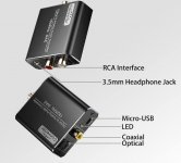
I was getting some ground loop noise (hum) while testing and tried to eliminate it. I bought a budget 2 channel TosLink DAC so I could break the electrical connection between my PC and filter + amps. Works great, no more noise, its silent now. However,... as soon as I listened to it, the audio quality was lacking.
I did a few quick loopback tests to the the PC and compared it to the PC soundcard (ALC889). I would expect any DAC to manage 20-20Khz flat and I can excuse the performance w,r,t SNR or THD as these usually require better P/S and layouts. This one surprised me so I posted a few pics. I suspect most of its problems can be fixed for <$5. It will be taken apart soon as I want to embed an optical interface into my active filter box.
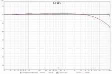
Pic#2 Compared to the PC's ALC889 using loopback. I can EQ the DAC flat but why start rolling off at 6Khz (unless its a reconstruction filter component error).
Pic#3 The THD with a cell phone charger. It's better than my speakers manage but not great for electronics, Sufficient for testing a speaker.
.
Attachments
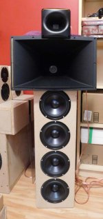
V11 - Quad woofers + ZXPC 11x17 + H07E
Finally, another version to try out. I was attempting to improve the midrange in my horn system by using a 2inch horn that was able to load and control to lower freq. The plots for these horns are in the previous posts. The ZXPC was advertised as 90x40 but realistically its closer 60x40. That's the narrowest polar I've tried, but it easily can handle a XO=725Hz as can the driver D2200Ph. The tweeter is a Dayton H07E with a Fane CD130. I was trying to understand why it behaves so differently from the other versions I have. That's easier to do in a simulator.
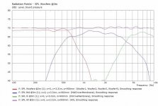
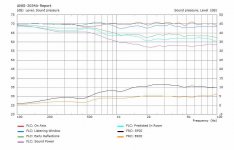
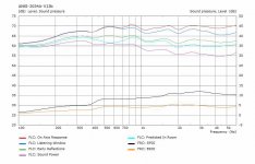
The AKABAK simulation uses LR4 XO [725, 4550Hz], some EQ (<+/-3dB), velocity curves from PWT CD measurements, and horn models based on physical measurements, the DSA175 motors were used with simple disc membrane. The polars are not normalized and the SPL curves show the driver contributions. The last graph is the ANSI-2034A (aka Spinorama) report.
This combination has a very different DI and power response from any of my previous versions. The midrange sounds very good as is the imaging (seperation and detail). What I noticed immediately is the power response difference compared to the cone+dome system. Initially it sounded unbalanced, like too much bass or not enough midrange (the system was EQ'd flattish with FIR phase correction). It could be that I'm used to something else or maybe the smaller temporary room I'm in. Still listening to it, and that's good.
Attachments

The mid / woofer crossover seems like it could do better with some EQ and change of slopes, the vertical lobe gets pulled down with a peak dip combination around that area. Might be worth looking at it to see if it changes your perception at all.
Possibly, I'll have a look at it, thanks. I also listen to the system without any EQ (just sensitivity adjustment) and I have the same impression. However the more I listen to it, the less I seem to fixate on it as well.
At least part of the V11 (2 posts earlier for details) power response problem I had was the room reinforcing LF too much. My mini woofer array also works better on floor. I'm temporarily using a smaller room and it makes quite a difference. So now I don't try to EQ the LF flat, I just let it fall off. Interestingly the 2 horns allow me to have relatively constant value DI~10 from ~1Khz to ~16Khz, or ~4 octaves out of 10.
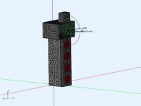
Pic#1 - the AKABAK model
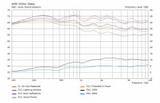
Pic#2 - spinorama report with no EQ applied, any ripples common to all curves can be EQ'd out
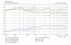
Pic#3 - spinorama report with EQ flattish. Power response changes a little, but DI is the same
Pic#4 - changed LF-XO to LR2 trying to "spread" the transition from woofer (DI=0) to horn (DI~10), no success
.
Pic#1 - the AKABAK model
Pic#2 - spinorama report with no EQ applied, any ripples common to all curves can be EQ'd out
Pic#3 - spinorama report with EQ flattish. Power response changes a little, but DI is the same
Pic#4 - changed LF-XO to LR2 trying to "spread" the transition from woofer (DI=0) to horn (DI~10), no success
.
Attachments
Wondering if a larger woofer (2x12inch) would help the power response. This sim had some problems at >6Khz but it still covers both XO points. The woofer polars are narrowing more but the power response is similar. Really no way around going from DI=1 to DI~=10. The DI slope in the transition from woofer to horn is a bit more shallow this time.
Attachments
Don - Could you elaborate a bit on what aspect of the power response needs help? It does not look to me like there is anything to complain about.Wondering if a larger woofer (2x12inch) would help the power response.
Compare these two speakers. The axial response is kept flattish is both cases.
V10 (built) has a smooth 5dB power drop across 200Hz-7Khz. It's at the expense of low DI, however it still images well and it sounds balanced.
V11 (built) has a 10dB power drop across 200Hz-7Khz, and most of that is actually across 500Hz-2Khz and it's noticable. The image and clarity are noticeably better than V10, but it's at the expense of sound power variation. So now I'm wondering how wide does that transition (DI=1 to 10) needs to be,?
Hence the V12 (sim only, above) which spreads (smooths) the transition (still 10dB, 500-2Khz) using larger woofers but maybe not enough.
Next, bass horn ? cardioid? . If I can get a smoother horn power transition to Schroeder (200Hz?) then maybe I won't care about keeping the axial response flat as the room will have to be considered as well.
Attachments


When the DI is flat the on axis and listening window may need to be shelved down a little. You could try -0.2dB /oct or a little more from the point where the DI flattens out. The PIR raises up from 2k which could be what you are hearing. Taking away treble or adding bass has a very similar effect on the tonal balance that is perceived. Sometimes the difference between off and right is not very much.
I understand your point now, Don. I was concentrating on the DI performance from 1000 Hz up, whereas you are concerned with a broader range.
Thanks for suggestions. I suspect that adding more MF-HF slope will further increase the sound power response difference and I think I need to decrease the difference. There are a few things to try, including your earlier suggestion to have a bank of shelf filters and just make the power response to my liking. Right now I'm still trying to find the differences in the spinorama curves that might explain it.When the DI is flat the on axis and listening window may need to be shelved down a little. You could try -0.2dB /oct or a little more from the point where the DI flattens out. The PIR raises up from 2k which could be what you are hearing. Taking away treble or adding bass has a very similar effect on the tonal balance that is perceived. Sometimes the difference between off and right is not very much.
Last edited:
Digging up speakers from the past. This is V8 (built) with updated simulation model and EQ. It uses a SH402 (90x40deg, DI~8) horn for the midrange. The sound power response is more even (than V11) and the difference ~5dB. The D290 driver and SH402 horn struggle to hit 725Hz. The horn looses pattern control and both need significant EQ (+8dB total ) to get a flattish response at XO. However the wider pattern also means more sound power given a flattish on axis response.
Attachments
Adding a bass horn V13 (conical flare) to reduce the LF beamwidth and smooth out the power response down to Schroeder.
The LF horn is driven by a 8" Silverflute model. It's not the best fit, but I already have a pair. The horn depth nearly matches the midrange horn depth so no time delay adjustment required. There is no magnitude EQ applied, however the common ripples could be EQ'd flattish. This a better sound power response than V11 or V12 and would be easy to make. Ideally the bass horn would be rotated 90deg, but this orientation still works to reduce the total beam width and not make the speaker footprint too large.
.
Attachments
The looks like simple conical wave guides (no loading) simply to guide the sound. I would suggest to try something like VotT to bring the LF part nearer to the horn. The voice only has opening angle to the sides and to the floor. I like the idea to have all drivers in one plane of sound origin.
Yes, it's very simple horn design to see if the idea had any merit. I plan on trying a few other LF horn designs (like the VotT you suggested earlier) to see if it can be improved. Curved walls could get tricky unless I build it up as a laminate of thin plys.
The sim was in 4pi space for ANSI. It should also be checked with a floor (2pi) as it may require changing the horn shape or woofer position. Either way this is an idea worth exploring further.
The sim was in 4pi space for ANSI. It should also be checked with a floor (2pi) as it may require changing the horn shape or woofer position. Either way this is an idea worth exploring further.
Next up V13b.
The bass horn is a exponential (Fc~300Hz). The LF axial response has not been made flat in order to level out the sound power. It would likely need some LF EQ to sound correct
The bass horn is a exponential (Fc~300Hz). The LF axial response has not been made flat in order to level out the sound power. It would likely need some LF EQ to sound correct
Attachments
- Home
- Loudspeakers
- Multi-Way
- Modular active 3 way - work in progress