A good guess, and that is possible 🙂 , but the RS52 is staying in the dome/cone configuration. I'm out of ideas to improve it and I like how it sounds.
The D2200Ph is for an upcoming custom horn to get better midrange for the horn configuration.
The D2200Ph is for an upcoming custom horn to get better midrange for the horn configuration.
In hindsight, it seems that I have totally messed in my original damping scheme for the woofer chambers. I have 12cm FG compressed to 8cm at the back wall behind my wall braces. Neither condition is optimal, so I opened up both towers and changed it to 8cm FG roughly in the middle. It does loosely touch the back in order to keep the FG in the middle.
A few pics from the simulation showing the pressures, and the last one from actual measurements before / after damping.
Even though the walls are short and braced I suspect they still vibrate. It would be interesting to use an accelerometer to determine the transfer function between the driver and walls. Then apply CLD to see it it can be improved / reduced. A suitable accelerometer (DR=+/-100G, BW=20Khz) would cost ~$100. Maybe later 🙂
.
Nice 🙂
... a 300Hz exponential horn (in foamboard) with predictable cutoff and load...
I had just decided that XPS foam was the way to build prototypes fast, and maybe make mould cores too.
And then I saw your nice work😉
How do you do your fabrication?
I had planned to hot wire cut but it looks like you bend? With heat?
Best wishes
David
Sufficient for the purpose 🙂
Foamboard (aka foamcore) is 5mm thick, paper clad both sides. I think @XRK971 introduced this technique and he uses alot of this stuff. Cheap, easy to work with and sold at any Dollar store. I have also used the XPS but I'm not set up for hot wire cutting, although I like the idea.
The wall dimensions are marked on the foamboard, then it's trimmed with a box cutter. Lateral score marks (weaken/cut paper on 1 side) allow you to easily bend the foamboard in one axis. Then you can hot glue the walls together. Any small gaps left from score and bending get filled in with interior latex caulking. I also caulk the corners and create a loft transition (hotglue+filler+caulk) to make a round throat transition. At least 2 layers of foam board with generous hot glue to create a mounting flange. Gets easy and fast once you've made a few.
Last edited:
"Cheap, easy to work with and sold at any Dollar store."
Oddly, doesn't seem to apply here. Does any Australian have a tip for where to pick up cheap and chonky foamcore?
Oddly, doesn't seem to apply here. Does any Australian have a tip for where to pick up cheap and chonky foamcore?
ZXPC 11x17x12in Horn
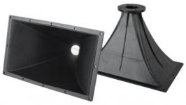
I picked up a pair of ZXPC horns (11"x17"x12", 2" throat) that looked like they would be suitable for my midrange horn. As typical, without a real spec, just some dimensions that looked promising.
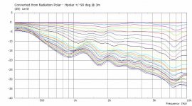
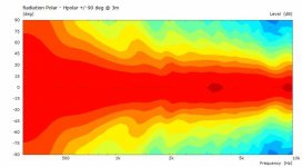
An AKABAK model was constructed from the physical measurements. It appears to loads low enough from the RadImp curve, and I know the D2200Ph can go low enough from previous Expo300 tests. Advertised as 90x40 it's probably closer to 70x40 based on the model. The horizontal is a little narrower than I would like, but it's still suitable.
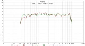
My usual room is in mid renovation so I can't use it to check the polars against the model. There is a quick on axis measurement (off a table edge) using the D2200Ph to check the FR range. The measurement (raw+EQ) was done with a UMIK1 and direct connection to a T-class amp (no caps, no XO). It looks good and I can't wait for a listening impression when I get my renovation finished.
I picked up a pair of ZXPC horns (11"x17"x12", 2" throat) that looked like they would be suitable for my midrange horn. As typical, without a real spec, just some dimensions that looked promising.
An AKABAK model was constructed from the physical measurements. It appears to loads low enough from the RadImp curve, and I know the D2200Ph can go low enough from previous Expo300 tests. Advertised as 90x40 it's probably closer to 70x40 based on the model. The horizontal is a little narrower than I would like, but it's still suitable.
My usual room is in mid renovation so I can't use it to check the polars against the model. There is a quick on axis measurement (off a table edge) using the D2200Ph to check the FR range. The measurement (raw+EQ) was done with a UMIK1 and direct connection to a T-class amp (no caps, no XO). It looks good and I can't wait for a listening impression when I get my renovation finished.
Attachments
-
 zxpcs-l500.jpg11.5 KB · Views: 339
 -
 ZXPC 11x17x12in + D2200Ph.jpg127.7 KB · Views: 239
 -
 ZXPC-11-17-12inHpolarCurves.jpg55.8 KB · Views: 248
 -
 ZXPC-11-17-12in-Hpolar.jpg24.1 KB · Views: 296
 -
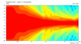 ZXPC-11-17-12in-Vpolar.jpg24.8 KB · Views: 284
 -
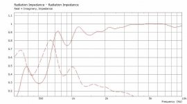 ZXPC-11-17-12in-RadImp.jpg37 KB · Views: 300
 -
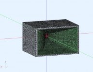 ZXPC-11-17-12in-model.jpg99.8 KB · Views: 292
Nice work! These horns always looked like good performers to me but not the plastic which would need some treatment.
It is interesting to see that from the impedance diagram real and imaginary part the first time intersect just below 700Hz and the horn provides still some load much lower.
It is interesting to see that from the impedance diagram real and imaginary part the first time intersect just below 700Hz and the horn provides still some load much lower.
Thanks.
True, however the Re part is still significant (~0.4) as low as 400Hz. The LF output drops (no EQ curve) as the Re decreases. At 400Hz I've applied 6dB to help it.
Agreed, the finish is OK, but the walls are thinner than I would like , so it will get some help when its finally put in a case. The driver is 3Kg so I would support it as well.
Last edited:
Contributing Factors, Midrange Horn System
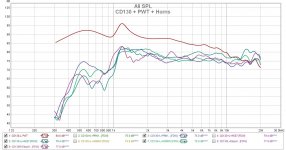
I'm looking again at my midrange horn solution. I can EQ them flatish over the range I currently need (725Hz-4550Hz) but was wondering about the contributing factors from the driver and the horn. I have budget PWT's for 1inch and 2inch drivers so I can measure use the PWT SPL (driver only) and compare it to the system (driver+horn). I also have AKABAK models for all my horns. These horns were physically measured to create the models. So they will be close, with some minor differences (hopefully) to indicate what the horn only is capable of.
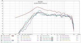
The pics attached show the raw data (no EQ) results of a Fane CD130Ti and PRV D290Py 1inch drivers on both PWT and horns. Neither the driver or the horns are suitable for my midrange. None of them can comfortably reach the lower freq limit I need. I currently adjust sensitivity (at the amps) and EQ them flatish. I need a 2inch system.
Attachments
Midrange horn measurement vs AKABAK simulation
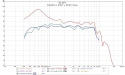
These are PWT and horn measurements on a 2inch system (PRV D2200Ph + ZXPC 11x17). This easily covers the midrange I need, and would allow me to go a little wider (600Hz-6Khz) as well. This looks very promising and will be used in my horn system.
The acoustic impedance of a PWT is constant over frequency (for a given tube diameter). So the PWT SPL measurements can be converted into a throat velocity profile and used in an AKABAK BEM simulation to predict the axial SPL response. Usually these BEM sims use a constant drive (velocity or acceleration) then normalize the results, which is sufficient for polar or directivity curves. However, a measured velocity profile can be used to predict the axial SPL response of the system without needing to create a LEM driver model. Since it's an actual measurement (ripples+resonances included) so it should be more accurate as well.
The pic below has PWT and system measurements (raw data) compared to the AKABAK system prediction using the D2200 throat velocity profile and the ZXPC horn model. The AKABAK horn model was created from physically measuring the actual horn, so I would expect some small differences. Overall the prediction looks good.
Attachments
Simply awesome!'tis the season, merry xmas to all !
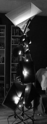
After a recent renovation, I had to temporarily relocate my audio to a new room. I hung my unused horns on a coat/hat rack (pole) to save space. It seemed fun to add a string of lights.
Audio-festivus anyone?
Have you never heard of Siren Head...you are going to scare the children lol! Happy Holidays Don, good stuff as usual. I don't know exactly what you are trying to do, but I know you are doing it right =)'tis the season, merry xmas to all !
After a recent renovation, I had to temporarily relocate my audio to a new room. I hung my unused horns on a coat/hat rack (pole) to save space. It seemed fun to add a string of lights.
Audio-festivus anyone?
hehe nice as usual Don! 🙂 seasons greetings! I dusted off the measurement gear for the first time in a long time. Just to measure my tweeters impedance and spl before I undergo ferro fluid replacement. Interested to see if there is much of a measurable change. They are 17 years old so figure the fluid has dried out to an extent.
I probably should have done measurements at differing power levels as well, but only did at around 1W level...
Tony.
I probably should have done measurements at differing power levels as well, but only did at around 1W level...
Tony.
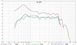
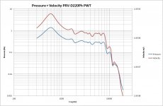
Oops! one of the important curves was missing. I'll repost it with the AKABAK sim prediction using the D2200 velocity profile. There is also another graph of the velocity and pressure curves for the D2200 in a PWT.Midrange horn measurement vs AKABAK simulation
These are PWT and horn measurements on a 2inch system (PRV D2200Ph + ZXPC 11x17). This easily covers the midrange I need, and would allow me to go a little wider (600Hz-6Khz) as well. This looks very promising and will be used in my horn system.
The acoustic impedance of a PWT is constant over frequency (for a given tube diameter). So the PWT SPL measurements can be converted into a throat velocity profile and used in an AKABAK BEM simulation to predict the axial SPL response. Usually these BEM sims use a constant drive (velocity or acceleration) then normalize the results, which is sufficient for polar or directivity curves. However, a measured velocity profile can be used to predict the axial SPL response of the system without needing to create a LEM driver model. Since it's an actual measurement (ripples+resonances included) so it should be more accurate as well.
The pic below has PWT and system measurements (raw data) compared to the AKABAK system prediction using the D2200 throat velocity profile and the ZXPC horn model. The AKABAK horn model was created from physically measuring the actual horn, so I would expect some small differences. Overall the prediction looks good.
Forgot to add. There will be some minor variations as the horn measurement was made without an enclosure and the AKABAK simulation had a minimal enclosure.
Attachments
Thanks for the movie reference, I've never heard of the Siren Head, looks interesting. You must have very eclectic taste in film 🙂 Eraser Head anyone? I was trying to show that you could use an AKABAK simulation to predict the horn's axial SPL curve shape using the driver's velocity profile. Usually the simulation is done with a constant drive (velocity or acceleration) which does not represent the actual driver.Have you never heard of Siren Head...you are going to scare the children lol! Happy Holidays Don, good stuff as usual. I don't know exactly what you are trying to do, but I know you are doing it right =)
hehe nice as usual Don! 🙂 seasons greetings! I dusted off the measurement gear for the first time in a long time. Just to measure my tweeters impedance and spl before I undergo ferro fluid replacement. Interested to see if there is much of a measurable change. They are 17 years old so figure the fluid has dried out to an extent.
I probably should have done measurements at differing power levels as well, but only did at around 1W level...
Tony.
Thanks. I have a vintage (34yrs) pair of Paradigm 11se mk1 that might have that issue. They still sound good but I don't have any baseline measurements. How would you detect dried (jelled) ferrofluid ?
Thanks, It would make a cool looking outdoor art piece as well. Maybe some tubes could be attached to the horns to make them resonate in the wind.Simply awesome!
Good question!! I just felt that the speakers had lost some of their magic. I did do some tests previously at different power levels which showed that the FR changed quite a bit depending on power level, whether or not that is just par for the course or could be related to sticky ferrofluid I'm not sure. I have before and (will have) after measurements of impedance. One tweeter, the impedance curve is somewhat wonky, I suspect the impedance curve is going to be the most telling.Thanks. I have a vintage (34yrs) pair of Paradigm 11se mk1 that might have that issue. They still sound good but I don't have any baseline measurements. How would you detect dried (jelled) ferrofluid ?
- Home
- Loudspeakers
- Multi-Way
- Modular active 3 way - work in progress