Hi @camplo
I've attached another pic of the speaker taken straight on. The numerous curves are giving an optical illusion when the speaker is rotated. Everything is symmetric.
Not surprising that our horn designs are similar size. If the goal is loading and wavefront control to ~300Hz then the sizes will end up similar as well. Ideally, I wanted to cover the ear's most sensitive bandwidth ~[300-6KHz, per ISO226 using a single driver and no XO in this region. That's a tall order for a single component, and tradeoffs are everywhere.
"Perpetual science project" , meaning the experiment never seems to end. When I notice a design defect, I attempt a solution, then soon after I find yet another issue to deal with. Although the rate of change seems to be slowing, so either I'm closer or tired 😉 I'll listen to the bullet tweeter for a while, and the science project will probably continue. 🙂
I listen relatively close (2m) but that's just a restriction of my current room. I have a basement waiting for me if I can ever clean it out, because I would prefer more distance.
The woofer array came from a slim tower design I was working on. It was used primarily to reduce floor bounce, As a bonus, using the floor as a mirror makes the vertical dimension appear 2x as large so the vertical control on the woofers is very good, with reduced midrange interference. The bare woofer array caused a "knee" in the system directivity slope at XO when I started using midrange horns, and I could not electronically correct the sound. So the woofer horn (fc=120Hz) was added to improve the directivity (power response) match to the horn(s) DI. The directivity curve is now a relatively constant slope, The woofer horn width was originally designed to match a WN425 horn, then I went bigger with the WN270. The woofer horn's height is 76cm, resulting from placing 4 woofers as close as possible using separate chambers. My listening chair puts my ear height at 1m, which is approx. the center of the midrange horn.
Thanks, I'll try the vocal stress later today. Its too early to start looping Barry White with volume.
Attachments


What is your listening experience? Do you need the tweeter?
Does the delay also work off axis?
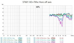
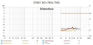
The XO was increased to 7Khz to reduce THD from the ST601. Pic#2 shows a smaller residual THD bump than XO@6Khz.
It appears (Pic#1) that the delay equalization holds until 20deg off axis. Starting somewhere between 20-25deg there is a dip around 7Khz which I'm assuming is XO related, but far enough off axis that I'm not motivated to chase it.
Attachments
I encourage you to try my Vocal stress test. I think vocals are the one of the most critiqued aspects of sound reproduction as it easily a reference that we are constantly being refreshed on, given that said listener is still a person who talks to other people in real life lol. Barry Whites voice exposes how well the bass and lower mids combine with the HF to form a singular sound. In particular the Intro where he's talking, Enjoy 😀
OK, I gave it a try. The voice position is stable and sound is consistent across the song. Was there something more specific I should look for? I also tried this on Tidal, it's available in CD (16b/44K) quality.
This is a fun track for dynamic range. It's a jazz'd version of the 2001 theme.
Optimal would be the voice sounding as if coming from a single point source. I wonder if some are more sensitive to this than others, but we know for sure, rooms n positioning of speaker and listener will change results as a result of bass modes and different doses of direct sound, etc. Another test would be Sine wave sweeping from HF to LF and judging whether or not the sound seems to emit from different points on the baffle and how significant the change is. The bass of Barry's voice during the intro is a great way to approach this aspect since we are natural trained to expect a single point source from vocals. The LF and HF are usually experiencing the most distance from each other. If the bass and Hf seem to emit from the same exact place, that would be optimal. If you really want to go all out, try it at high spl according to your expectations or tolerance. At 2 meters and a 500hz -600hz I personally could sense the vocals coming from 2 difference places on the baffle thats without saying 100% why. I simply felt I can tell where the spl was coming from vs spectrum. My CTC is around 20inches. I think I am just really sensitive to this aspect but now that you mention it "As a bonus, using the floor as a mirror makes the vertical dimension appear 2x as large " this could of also been apart of the issue.OK, I gave it a try. The voice position is stable and sound is consistent across the song. Was there something more specific I should look for? I also tried this on Tidal, it's available in CD (16b/44K) quality.
If you try the signal sweep approach, Use REWs feature that allows the signal to track the mouse dragging on the RTA, Move above and below the crossover point, to test that area, and possibly 7khz to 150hz.
If you have to try very hard to expose this trait, then its definitely a win.
Last edited:
Woofer Bi-amp for sensitivity improvement
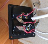
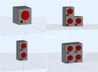
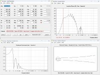
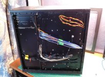
I have 4 woofers that are currently in a 2S2P configuration to keep the load impedance high enough for a typical amplifier channel. I would prefer to attach drivers directly in a 4P fashion, but this would require bi-amping the woofer array. I have spare amp channels and the woofer cabinets were wired for bi-amping, and its easy to reconnect them (Pic#1) in a 2P+2P using 2 channels that's effectively 4P. The motive for higher woofer sensitivity is to get a better match to the horn's sensitivity (less attn required).
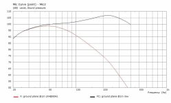
I ran a quick Hornresp sim to verify there would no adverse consequences of the rewire. The responses were imported into REW (pic#2) because it's easier to see multiple curves. The 2S2P config has an avg 96dB / 2.83Vrms sensitivity (was measured at 95dB, but close enough). Changing to 4P config would provide avg 103dB / 2.83Vrms sensitivity on the woofer horn.
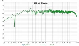
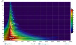
The system (WMT) was rebalanced to 103dB/2.83Vrms sensitivity by using less attn on the midrange horn and bullet tweeter, The system was measured in my treated room because I really don't have an option to measure outdoors. Raw FR measurements (no smoothing, no gating) are provided (pic#3) as well as the wavelet spectrum for decay times (pic#4). My single subwoofer is languishing at 92dB/2.83Vrms and even with moderate boost is just used to control the VLF roll off. I still need a solution to both the VLF levels and VLF room decay times. Overall the system change is noticed immediately as being louder for the same volume setting and it appears more dynamic (less horn attenuation). The noise floor of my amplifiers is more noticeable when I'm close to the speakers, but not noticeable during playback or between tracks. Look good so far, but it takes me some time to appreciate nuances.
Attachments

... more subs ?
How many more subs would I need to get similar sensitivity (103dB @ 2.83Vrms) instead of just boosting the gain on a single sub ?
If I boost the drive (gain) to the current sub (fc=28Hz, 44x38x48cm OD) from 92dB @2.83Vrms up to 103dB I would need 2.83*10^(11/20)= 10Vrms and P=10^2/3.3=30.3 watts and it displaces 3mm peak in passband.
If I add more subwoofers of the same design, I would need qty 4. The BEM + LEM sim was built using AKABAK's built in primitives and was used to check SPL addition and floor coupling (2Pi space) of the slightly raised subwoofers. Qty 4 subwoofers use P=4*(2.83V^2)/3.3R = 9.7W and displaces 0.8mm peak in passband for 103dB. If I had more subwoofers I would probably distribute them to help even out the room.
[edit] the DCS305 (12in) subs have LR4@80Hz filters
Attachments

Last edited:
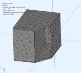
After reading some of @camplo Sub topologies thread there were some configurations that might be suitable for me.
This sim is a hybrid LEM (motor+chambers) BEM (radiators+exterior) with 2 drivers (same DCS305) placed at 90deg in a bass reflex config. There is little benefit over the BR dual cabinets when Fc=80Hz, but maybe some benefit at higher freq.
This sim is a hybrid LEM (motor+chambers) BEM (radiators+exterior) with 2 drivers (same DCS305) placed at 90deg in a bass reflex config. There is little benefit over the BR dual cabinets when Fc=80Hz, but maybe some benefit at higher freq.
Attachments
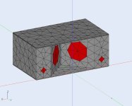
The mouth is [W60,H40,D30cm]. The model is simplified (hybrid, fast) so it won't show rear chamber resonances/interactions. I just wanted to see if there were any external front radiation issues and what (if any) gain was possible. Once I settle on a configuration, then I do more detailed simulations, including the rear chamber in BEM.
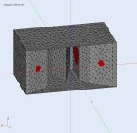
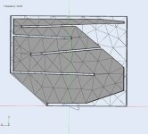
The next model up is the horizontal opposed woofers with the "V" wedge separator. The Hornresp model of it looks very promising. However I'm having a few difficulties in the Akabak model, but it will be posted soon.
The next model up is the horizontal opposed woofers with the "V" wedge separator. The Hornresp model of it looks very promising. However I'm having a few difficulties in the Akabak model, but it will be posted soon.
Another topology, using horizontally opposed drivers (vibration cancel) with a wedge between them for compression and building the horn (offset drivers).
This cabinet has a larger and deeper integral horn that loads the drivers at a lower freq than the previous example (starts loading @~100Hz). Unfortunately it still does not offer any advantage for me in the lower freq that I use but it does help in the higher freq. I used a simple inductance model for these simulations, but it would be better to use semi-inductance method and the higher freq peaks would be lower.
This cabinet has a larger and deeper integral horn that loads the drivers at a lower freq than the previous example (starts loading @~100Hz). Unfortunately it still does not offer any advantage for me in the lower freq that I use but it does help in the higher freq. I used a simple inductance model for these simulations, but it would be better to use semi-inductance method and the higher freq peaks would be lower.
Attachments
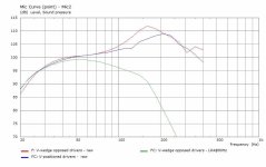
Many thanks for this investigation. The last performs almost spherical. Much better than expected initially.
Thanks, it was fun to do. BTW to sim that in Akabak required placing a subdomain boundary at the mouth.
Impaired Subwoofer Horn
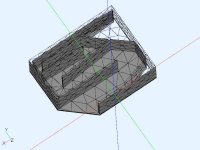
Another option to get higher subwoofer sensitivity is to load the driver with a horn. This is usually not done because a "proper" subwoofer horn would need to be around 4m long with a mouth of 40000cm^2. However, the last part of the horn is where the size gets large, most of the path has reasonable dimensions. So why not use the flare rate for loading and truncate to horn to avoid the large mouth. The large mouth is required for graceful termination and directivity, however both are not critical for VLF omnidirectional freqs.
The basic profile was calculated by Hornresp (see attached) then an Akabak model was constructed with as much of the horn path I could fit into a reasonable sized box [W800cm x H640cm x D620cm]. The folded horn is almost 3m long but the mouth had to be truncated to 2000cm^2 and the last 40cm does not flare as fast as it should. It comes very close to want I wanted,, F3=34Hz, and sensitivity 102dB @ 2.83Vrms @1m in 2Pi space. More likely it would be on the floor against a wall so in 1Pi space that's 108dB @ 2.83Vrms. A lower F3 would be preferred but I would need another 50cm of horn path and a significantly larger mouth. Compromises everywhere.
The pressure field diagrams of the horn were animated to better see the pressure changes in the horn over freq. Getting a usable viewable pressure scale is tricky because the pressure range is so large. The horn internal pressures are much higher than the external pressures. Its clear my truncated horn causes turbulence near the mouth, but its not apparent at a distance and I get the horn gain.
Attachments

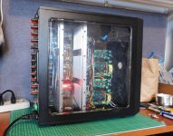
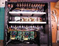
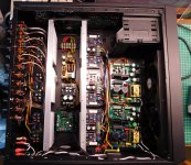
Another Amplifier
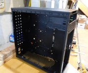
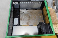
It's still too cold to work in the garage, so I've added another amp for comparison. I've used a TriPath amp for a few years and wanted to compare it to a chip amp class A/B.I used a PC midtower case, removed some metal and added some metal to suit the new parts mount. There are 6 channels LM3886 (Bipolar) and 6 channels TDA7494 (MOSFET). Their heatsinks face inward to a 12x12x42cm plenum with temp controlled push-pull 12cm fans. It can also run convection cooled without fans but I'm not sure what the max fanless power would be, Separate supplies +/-30VDC each for section [HF,Mid] and [VLF, LF]. Sounds very good but there are some subtle difference but nothing that jumps out. Something new to listen to.
Attachments
-
 DSCN2707r.JPG312.3 KB · Views: 65
 -
 DSCN2706r.JPG285.5 KB · Views: 74
 -
 DSCN2704r.JPG306.4 KB · Views: 72
 -
 DSCN2724r.jpg347.5 KB · Views: 66
 -
 DSCN2723r.JPG345 KB · Views: 72
 -
 DSCN2717r.JPG297.4 KB · Views: 63
 -
 DSCN2694r.JPG239.9 KB · Views: 59
 -
 DSCN2685r.JPG193.9 KB · Views: 58
 -
 DSCN2676r.JPG180.5 KB · Views: 62
Actually yes, the 2x5.25" drive bay (empty) and original PC control panel (on/off, USB, audio) are still intact.
LOL, I thought I was the only one who'd repurposed a PC case as an amp chassis. Nice work and very neat.
My next build is still going to use pro amps again, but then will get 12 channels of Hyped. Case will be a variation on this theme. Pics when it happens.
My next build is still going to use pro amps again, but then will get 12 channels of Hyped. Case will be a variation on this theme. Pics when it happens.
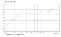
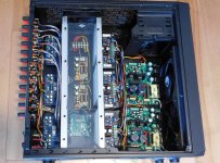
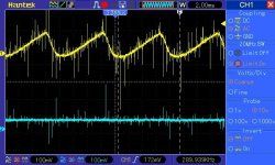
Background noise reduction
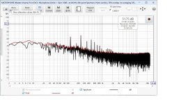
There is background noise in my class AB chip amp that definitely has harmonics. After investigating it a bit, it turns out that the PSRR of these particular amps is poor. Could be the board or "generic" equivalent chips but it's related to power supply ripple (both have it). I measured the speaker noise (see pic) using a UMIK mic and all harmonics are multiples of 120Hz (rectified 60Hz) from a switching supply ??? 😕 It seems these particular chip amps only have PSRR~35dB @120Hz but the data sheet of the original states PSRR>80dB @120Hz.It's easy enough to remove the supply ripple (200mV p-p triangle) using a linear regulator. The MF+HF uses little power and these LM317/LM337 regulators are sufficient to provide about 1.5A (30w). The before/after pic is attached showing the pre and post difference. The LM regulators have about ~70dB@120Hz attenuation which is less than the original chip amplifiers PSRR>80dB. There is still some HF hash left over ,so some EMI filters were used and the Vdd + Vss lines shown below. There are still a few noise spikes that I think are from cascading common mode chokes (single power return line) so cancellation is not perfect. The MF and HF horns are audibly silent (nearfield) during the silent periods. The VLF+LF section will use this regulator board, modified to use a pass transistor, for more current.
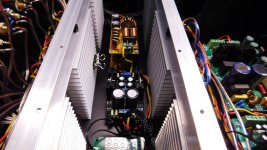
A few pics to show the regulator (set to +/-28VDC) and stacked EMI filters in the cooling plenum.
Attachments

- Home
- Loudspeakers
- Multi-Way
- Modular active 3 way - work in progress