Nice topology for an all horn system. Only an observation --if you don't mind-- I would suspend the mdbass horn one foot from the floor (making it less rectangular, more square) so the sound would be cleaner in the sensible midbass region.
Looks really nice! How low does the front horn is loading? It is not conical - right? The side walls/guides seem to have a slight curvature.
Comments and suggestions always welcome.Nice topology for an all horn system. Only an observation --if you don't mind-- I would suspend the mdbass horn one foot from the floor (making it less rectangular, more square) so the sound would be cleaner in the sensible midbass region.
There were compromises made for the bass horn. The height was needed to place the midrange horn at the preferred height (90cm). It also had to work (benefit) with the floor to minimize floor bounce. The one physical thing I can't change is the floor between me and the speaker. It could be made wider but I'm not convinced I need to because the mouth is large enough for pattern control. I only needed it to reduce the beamwidth and hence acoustic power. If I moved it off the floor it would reduce the LF gain (4pi radiation) and allow more floor bounce.
Looks really nice! How low does the front horn is loading? It is not conical - right? The side walls/guides seem to have a slight curvature.
Thanks.
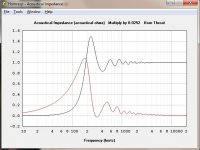
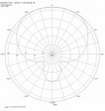
The side walls are curved, and it's a Hypex T=0.7, Fc=120Hz as built (minor variation from the previous sim due to actual wood dimensions). I did try a Conic in an earlier sim version but it throws polar side spurs without a mouth termination (and it's already large), and the loading was poor.
This is the Hornresp RadImp loading prediction for the Hypex built. The RadImp peak at 230Hz actually shows up in the SPL measurement and was EQ'd flattish.
Attachments
The reason for my suggestion is that I already experimented both cases. Quite an improvement in localisation --especially on cello sound and men voices-- and lack of cavernous tone (which happens because bouncing reflections in such large horn (90cm) compared to upper midbass tones (just under 500Hz, lambda is about 70cm)). You don't really need LF gain in 200-500Hz but sure need clarity. Just try elevate it from the floor, maybe make a mockup, an idea smaller (under 70cm overal), to observe the difference.
Let a proper subwoofer serve spectrum under 120Hz, but don't try to lower the midbass horn to get there, it would get muddy. If you get "greedy" by trying to solve all at once, you lose more than you gain. I am sorry if it sounds condescending, but it took me many years and lots of money to learn these things.
Let a proper subwoofer serve spectrum under 120Hz, but don't try to lower the midbass horn to get there, it would get muddy. If you get "greedy" by trying to solve all at once, you lose more than you gain. I am sorry if it sounds condescending, but it took me many years and lots of money to learn these things.
No problem with different views and experiences.
The woofer array reduces floor bounce (and increases clarity IMO) in both simulations and measured results (SPL + THD). Some speakers have too much BSC and lifting them helps balance things. I've designed with the floor as a necessary component. I agree with your subwoofer comments and I typically use 2 subs for <80Hz. I'm not looking after LF gain but I'll use it, if its free 🙂 , I'm actually trying to better match the beamwidth of the bass horn to the mid horn, so the acoustic power is similar.
The woofer array reduces floor bounce (and increases clarity IMO) in both simulations and measured results (SPL + THD). Some speakers have too much BSC and lifting them helps balance things. I've designed with the floor as a necessary component. I agree with your subwoofer comments and I typically use 2 subs for <80Hz. I'm not looking after LF gain but I'll use it, if its free 🙂 , I'm actually trying to better match the beamwidth of the bass horn to the mid horn, so the acoustic power is similar.
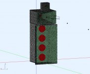
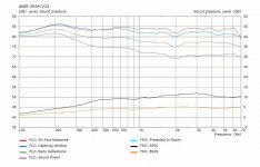
Just to finish the data set for the V13. The model, simulation results and spinorma report from the AKABAK simulation. The transition from woofer to mid horn is smoother now (less "step") and it sounds more balanced. This is the highest DI speaker I've made.
The actual measured on axis response and THD shows the horns are fairly clean. However my current room is not sufficient to accurately measure the bass response.
.
The actual measured on axis response and THD shows the horns are fairly clean. However my current room is not sufficient to accurately measure the bass response.
.
Attachments


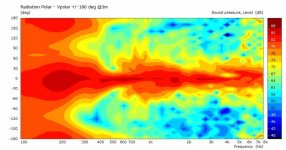

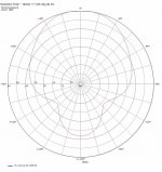
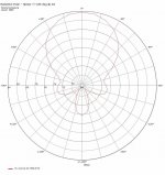
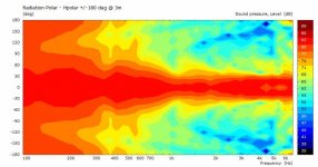
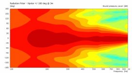
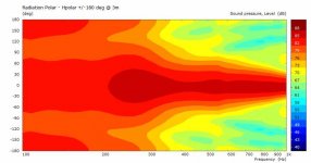
The bass response is easier to see in polar plots from the simulation. It made me wonder if I could increase the the bass horn DI a little more. These are the polar plots that show the region from 100-300Hz that could be improved to make it look like the 400-600Hz region. I could make the horn bigger (not desirable) or maybe an active cardioid design that applies pressure at the horn side edges. Might be an interesting simulation.
.
.
Attachments


Indeed, very impressive! Does it sound also subjectively different in lower mids compared to other speakers you have?
^ I keep these 3 speakers, because they behave so differently (all were EQ'd flat on axis).
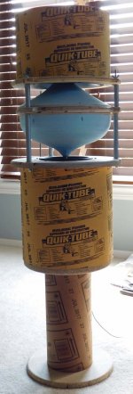
pic #1 : omnidirectional : no directivity, sprays the room, imaging is OK, power response is OK, I like this with acoustic instruments. It has a single 8inch woofer and a reflector so lower mids are not as defined as I would prefer. Needs a pedestal stand and >1m spacing from any wall.
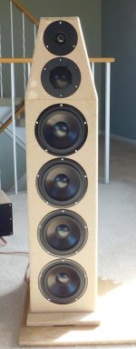
pic#2 : conventional monopole, low directivity, has the best (even) power response (balanced), with good imaging and detail. The lower mids are very good because of more woofer Sd (than pic#1) and the array working with the floor (IMO).
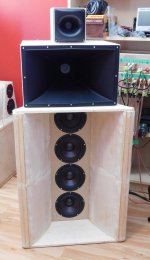
pic#3 : full horn, high directivity, power response is OK, has the best imaging and detail. The lower mids are excellent and the bass horn improves transients (punch) and detail compared to pic#2.
pic #1 : omnidirectional : no directivity, sprays the room, imaging is OK, power response is OK, I like this with acoustic instruments. It has a single 8inch woofer and a reflector so lower mids are not as defined as I would prefer. Needs a pedestal stand and >1m spacing from any wall.
pic#2 : conventional monopole, low directivity, has the best (even) power response (balanced), with good imaging and detail. The lower mids are very good because of more woofer Sd (than pic#1) and the array working with the floor (IMO).
pic#3 : full horn, high directivity, power response is OK, has the best imaging and detail. The lower mids are excellent and the bass horn improves transients (punch) and detail compared to pic#2.
Attachments
Don - That is some serious directivity from 300 Hz up. Technically impressive.
Thanks, The V13 bass horn removed the power response "knee" from the earlier spinorama report V11, V12.
I wonder about how much lower (freq) I can achieve a high DI. Simulations are cheap 🙂 .
Just to see how wide I could get the midrange band for V13 (D2200 + ZXPC). These tests were configured using a DSP-408.
pic#1 : Hpolar from AKABAK with midrange XO [500, 6K], with better EQ this time
pic#2 : Filter templates (RePhase) and measured output, with EQ
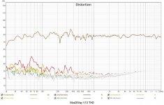
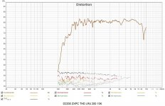
pic#3 : THD to check the driver
pic#1 : Hpolar from AKABAK with midrange XO [500, 6K], with better EQ this time
pic#2 : Filter templates (RePhase) and measured output, with EQ
pic#3 : THD to check the driver
Attachments
It seems to have no problems shwoing up yet. Lower the 500 LR to se where it fails. Check also THD-line in Distortion tab.
Attachments
Last edited:
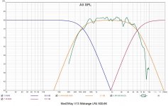
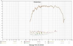
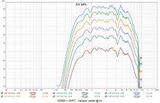
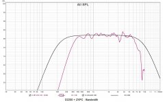
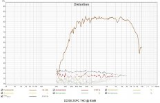
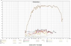
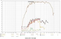
A few more graphs. I think 500-6K is about the max usable range and all I require is 100dB max, which it easily does. I'm not sure about the actual diaphragm excursion under these conditions.
Pic#1 : LR4[500-6K] various SPL levels
Pic#2 : LR4[200-10K] to see where it falls off a cliff
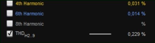
Pic#3-5 : LR4[500-6K] THD at various SPL levels
Pic#1 : LR4[500-6K] various SPL levels
Pic#2 : LR4[200-10K] to see where it falls off a cliff
Pic#3-5 : LR4[500-6K] THD at various SPL levels
Attachments

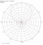
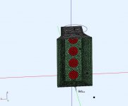
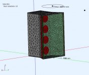
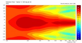
The bass horn has good directivity >300Hz but I interested in extending it lower into the 100-300Hz range. All these methods will involve active drivers to shape the beam width, using standard filters and time delays. The main woofer chambers are always sealed. Pic#4 shows a beam shaping improvement using a thin (3cm) horn mouth edge port. It's just not enough improvement, so we'll place shaping radiators in other locations, and try again.
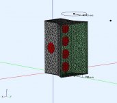
pic#1,2 - baseline V14 (same as V13) model and Hpolar
pic#3,4,5,6 - V14.1 horn edge port with Hpolar's
pic#1,2 - baseline V14 (same as V13) model and Hpolar
pic#3,4,5,6 - V14.1 horn edge port with Hpolar's
Attachments

With side ports (still active driven). A little better, but still not enough improvement.
.
.
Attachments

- Home
- Loudspeakers
- Multi-Way
- Modular active 3 way - work in progress