Interesting, those polars for the brick wall filter may show why people object to them! 🙂
Tony.
That got me thinking about some other measurements that I could make to understand the differences between the crossovers and the dome / horn solutions that I have.
ANSI-2034A spinorama
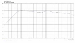
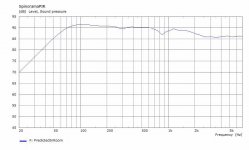
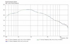
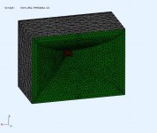
These are ANSI-2034A (aka Spinorama) measurements for the cone/dome system. It's from an ABEC simulation which is probably the only way for me to do a 360deg vertical and horizontal spin and measurement of this speaker.
The sim range is 20Hz-12Khz limited at the high end by the model mesh resolution. The XO is the standard LR4 IIR [725,4550] and the speaker was EQ'd flattish on axis. I also changed the woofer polarity because (I think) the mini array of woofers integrates better due to the distance to the midrange. The polars are also included as the measurement distance (2m) has changed for ANSI, the drive levels have changed, and the scales were adjusted.
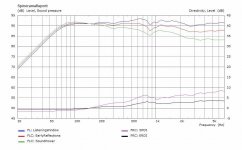
The reports are ANSI-2034A format. Nothing surprising in them, but I like the idea of standardized measurements for comparisons. This is a low directivity speaker due to the small driver sizes. I was surprised that a flat listening window response resulted in a downward sloping predicted room response. Interesting stuff 🙂 I wonder how this compares to the horn system?
.
These are ANSI-2034A (aka Spinorama) measurements for the cone/dome system. It's from an ABEC simulation which is probably the only way for me to do a 360deg vertical and horizontal spin and measurement of this speaker.
The sim range is 20Hz-12Khz limited at the high end by the model mesh resolution. The XO is the standard LR4 IIR [725,4550] and the speaker was EQ'd flattish on axis. I also changed the woofer polarity because (I think) the mini array of woofers integrates better due to the distance to the midrange. The polars are also included as the measurement distance (2m) has changed for ANSI, the drive levels have changed, and the scales were adjusted.
The reports are ANSI-2034A format. Nothing surprising in them, but I like the idea of standardized measurements for comparisons. This is a low directivity speaker due to the small driver sizes. I was surprised that a flat listening window response resulted in a downward sloping predicted room response. Interesting stuff 🙂 I wonder how this compares to the horn system?
.
Attachments
Last edited:
Hi Don, nice work, just needs a small correction to make it easier for people to find, as it deserves.These are ANSI-2034A.
It's a CTA/CEA standard not ANSI, there is no ANSI 2034.
Available thru the ANSI website (at a steep price) but downloadable from CTA free.
Best wishes
David
Last edited:
The DI is rising with frequency which is why the in room response drops when the on axis is flat.I was surprised that a flat listening window response resulted in a downward sloping predicted room response. Interesting stuff 🙂
.
If the DI is flat and the on axis flat, the in room won't drop. Which is why all flat DI speakers tend to be voiced with a falling on axis curve to compensate.
It's a CTA/CEA standard not ANSI, there is no ANSI 2034.
If we are trying to get it right we might as well go to the source 🙂
They call it
Standard Method of Measurement for In-Home Loudspeakers (ANSI/CTA-2034
– Consumer Technology Association(R)
Attachments
Hi Don, nice work, just needs a small correction to make it easier for people to find, as it deserves.
It's a CTA/CEA standard not ANSI, there is no ANSI 2034.
Available thru the ANSI website (at a steep price) but downloadable from CTA free.
Best wishes
David
Thanks, I had the 2015 version and I shortened the spec's title. I don'tr understood why CTA is free and ANSI costs ??
The DI is rising with frequency which is why the in room response drops when the on axis is flat.
If the DI is flat and the on axis flat, the in room won't drop. Which is why all flat DI speakers tend to be voiced with a falling on axis curve to compensate.
Makes sense. I'm more curious now about how it compares to my horn solution. I just need to build models for these horns.
fluid said:If we are trying to get it right we might as well go to the source
Thanks. Just downloaded the 2020 version and the coefficients look the same.
.
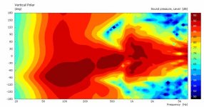
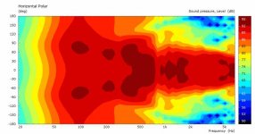
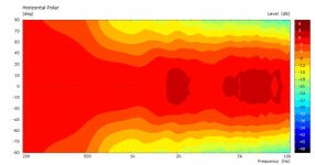
First of the horn solutions with Spinorama data.
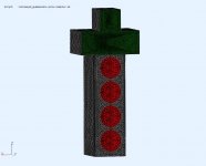
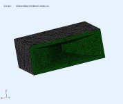
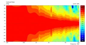
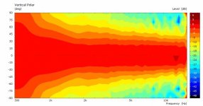
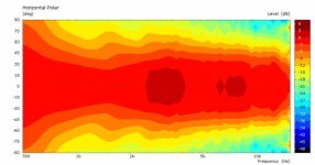
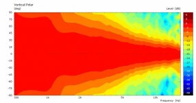
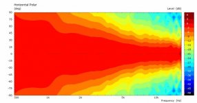
Higher directivity as expected. In the actual speaker, I shifted the horn positions to align wavefronts on axis, but this impacts the polar response. In the sim model I can EQ flattish and add time delay to get the wavefronts aligned. You can also see the DI bump between the woofers and mid horn.
.
Higher directivity as expected. In the actual speaker, I shifted the horn positions to align wavefronts on axis, but this impacts the polar response. In the sim model I can EQ flattish and add time delay to get the wavefronts aligned. You can also see the DI bump between the woofers and mid horn.
.
Attachments
Is that the vertical lobe tilt or is that from the crossover?I shifted the horn positions to align wavefronts on axis, but this impacts the polar response.
In the sim, the XO is a LR4, with some time delay. So everything is aligned to the baffle. Still have the LR4 lobes. The LF vertical tilt is due to the position of my "on axis" definition (mid horn).
In the actual build there is also an LR4 but I shifted the horns to get them time aligned to the bafffle. It means there is a horizontal off axis path difference (interferences) when I measure the polars.
In the actual build there is also an LR4 but I shifted the horns to get them time aligned to the bafffle. It means there is a horizontal off axis path difference (interferences) when I measure the polars.
CTA is a USA foundation Who We Are
The Consumer Technology Association (CTA)® convenes companies of every size and specialty in the technology industry to move us all forward. CTA is the trade association representing the $422 billion U.S. consumer technology industry, which supports more than 18 million U.S. jobs.
CTA, formerly the Consumer Electronic Assn. (CEA), makes an ongoing effort to grow the CE industry by developing essential industry standards to enable interoperability between new products hitting the market and existing devices. With more than 70 committees, subcommittees and working groups and roughly 1,100 participants, the CTA Technology & Standards program maintains an unmatched reputation as a credible and flexible standards making body accredited by the American National Standards Institute (ANSI).
ANSI is an organization in USA too American National Standards Institute - ANSI Home
THE AMERICAN NATIONAL STANDARDS INSTITUTE OVERSEES STANDARDS AND CONFORMITY ASSESSMENT ACTIVITIES IN THE UNITED STATES.
ANSI's mission is to enhance both the global competitiveness of U.S. business and the U.S. quality of life by promoting and facilitating voluntary consensus standards and conformity assessment systems, and safeguarding their integrity. Encompassing nearly every industry, the Institute represents the diverse interests of more than 270,000 companies and organizations, and 30 million professionals worldwide.
IEC is international foundation based in Switzerland Homepage | IEC
IEC International Standards are essential for quality and risk management; they help researchers understand the value of innovation and allow manufacturers to produce products of consistent quality and performance. IEC International Standards are always used by technical experts; they are always voluntary and based on the international consensus of experts from many countries.
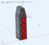
SH402 model
Taking a step back to generate models of the horns I have. I find it surprising that many manufacturers don't supply this very basic info.
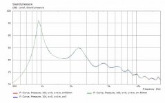
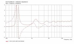
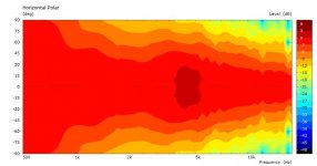
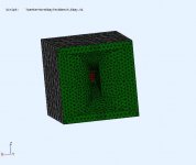
First up is the B52 SH402 which is rumored to be a clone of the JBL2730. These models are based on physically measuring the horn to create a CAD model. The models are placed in simple enclosures (like I built) for the simulation. Caveat - I would view them as approximations, since I don't have the original math profiles that created them.
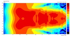
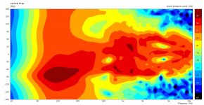
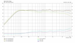
Model comparison to actual measurements : The horn is approx 90Hx50V as advertised, and requires EQ correlated to the response bumps shown. It also has the horizontal directivity dip around 1Khz.
Taking a step back to generate models of the horns I have. I find it surprising that many manufacturers don't supply this very basic info.
First up is the B52 SH402 which is rumored to be a clone of the JBL2730. These models are based on physically measuring the horn to create a CAD model. The models are placed in simple enclosures (like I built) for the simulation. Caveat - I would view them as approximations, since I don't have the original math profiles that created them.
Model comparison to actual measurements : The horn is approx 90Hx50V as advertised, and requires EQ correlated to the response bumps shown. It also has the horizontal directivity dip around 1Khz.
Attachments
Random Ebay Horn
Next up is some random horn I picked up off Ebay. Its probably a clone, but I can't seem to find the original one that looks like this. Any guesses from the horn aficionados ??
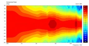
Comments : I only use this >4K5 and the polars looks about right at 80Hx50V and the required EQ seems about right. Unusual design with a long throat and abrupt short flare at the mouth.
.
Next up is some random horn I picked up off Ebay. Its probably a clone, but I can't seem to find the original one that looks like this. Any guesses from the horn aficionados ??
Comments : I only use this >4K5 and the polars looks about right at 80Hx50V and the required EQ seems about right. Unusual design with a long throat and abrupt short flare at the mouth.
.
Attachments

Dayton H10RW
I don't use it in this project because I wanted to have approx H:V=2:1 . It's included for comparison. It's about 60deg coverage.
.
I don't use it in this project because I wanted to have approx H:V=2:1 . It's included for comparison. It's about 60deg coverage.
.
Attachments
B52 PHRN-1014
This is good but did not go low enough. Required lots of EQ to get 725Hz. Coverage is about right 90x50.
.
This is good but did not go low enough. Required lots of EQ to get 725Hz. Coverage is about right 90x50.
.
Attachments

Last edited:
Dayton H07E
Another, works well as a tweeter. I used it from 4K5. Avg 60x50 coverage.
.
Another, works well as a tweeter. I used it from 4K5. Avg 60x50 coverage.
.
Attachments
PWT on a budget
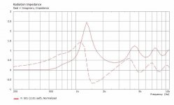
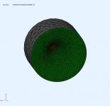
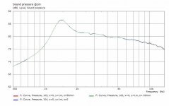
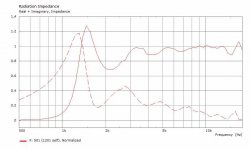
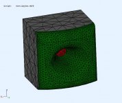
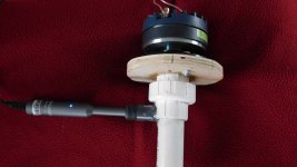
A PWT is another piece of test gear that I've always wanted to experiment with. Mostly it would be to create CD models for simulation. Manufacturers seem provide graphs (SPL+Zo) of their CD mounted to an unspecified or custom horn.
This PWT is as budget as it gets. Made from 10ft (cut to 2.5m) 1-inch PCV SCH40 pipe, a socket union, and and 0.5inch nipple. The nipple was half filled with hot glued, then drilled out to snuggly fit a UMIK-1 mic. The mounting flange plywood with a gasket made from rubber cork sheet. The union allows removing the tube or rotating the CD for measurement averaging. Total cost ~$20 CDN, as shown in the first pic.
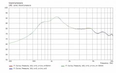
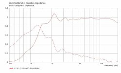
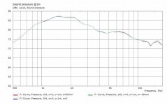
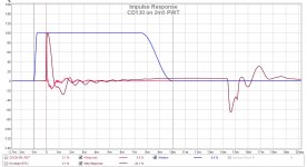
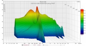
Measurements are gated at 10ms although the first reflection is at ~14.5ms (ie. ~5m) as shown in pic@2 impulse response. The CD130 is a small format driver spec'd from 2K-18K which seems about right (pic#3). The CSD shows the minor ~8K and ~12K resonances that I've seen when connected to various horns. The larger 1K1 resonance is not a problem for me as I would never use it that low.
.
A PWT is another piece of test gear that I've always wanted to experiment with. Mostly it would be to create CD models for simulation. Manufacturers seem provide graphs (SPL+Zo) of their CD mounted to an unspecified or custom horn.
This PWT is as budget as it gets. Made from 10ft (cut to 2.5m) 1-inch PCV SCH40 pipe, a socket union, and and 0.5inch nipple. The nipple was half filled with hot glued, then drilled out to snuggly fit a UMIK-1 mic. The mounting flange plywood with a gasket made from rubber cork sheet. The union allows removing the tube or rotating the CD for measurement averaging. Total cost ~$20 CDN, as shown in the first pic.
Measurements are gated at 10ms although the first reflection is at ~14.5ms (ie. ~5m) as shown in pic@2 impulse response. The CD130 is a small format driver spec'd from 2K-18K which seems about right (pic#3). The CSD shows the minor ~8K and ~12K resonances that I've seen when connected to various horns. The larger 1K1 resonance is not a problem for me as I would never use it that low.
.
Attachments

A PWT is another piece...
Nice work (as usual!) my compliments - any plans to stuff with sound absorbent material?
The AES document covers how to smoothly transition the absorption to kill the reflections but maybe it was more relevant back in the Bruel & Kjaer swept sine era and not worth the effort now we can so easily time window?
But the time window does limit the frequency resolution, naturally, and my naive expectation is that a 10 mS window will not permit CEA/CTA recommended 1/20 octave resolution below about 3 kHz.
What is your view on this?
Best wishes
David
Last edited:
Hi David,
Thanks.
This is not a SWR tube like AES-01id-2012-f (or it's newer version). It would be too difficult for me to make a long open cell foam wedge and then calibrate it. It has some advantages (and more requirements) so I simplified the method to suit my needs.
The tube must be empty and open, no damping, and a gated measurement (REW). Even at 10ms gate, REW will calc down to 100Hz and I smoothed to 1/24 octave. Using the throat SPL and the acoustic impedance of the air tube, I can calculate the throat velocity profile. So the CD model is really simple using throat velocity for BEM, and the electrical impedance for the LEM side.
.
This is not a SWR tube like AES-01id-2012-f (or it's newer version). It would be too difficult for me to make...then calibrate
The AES standard is still a Plane Wave Tube, not sure exactly what you mean by an SWR tube.
I don't think there is a need to do any of the old SWR stuff mentioned in the standard.
More modern Time domain analysis should make it fairly easy to check the absorption of the end reflection, just look at the impulse response.
At least, that's my intention if I ever build the one I have planned.
I also plan simply to stuff it with fibreglass, seems like it should not be too hard to push small pieces from the far end and they should slowly start to pile up more densely down the axis.
Only needs a little scrap fibreglass so at least it's essentially free to experiment.
Just stuff it incrementally more densely and the inverted end reflection should reduce until it disappears, stop before an in-phase reflection appears.
A nice double check is that the response shouldn't alter if the end is then closed.
I hope it's as simple as it sounds.
Even at 10ms gate, REW will calc down to 100Hz and I smoothed to 1/24 octave.
My naive expectation is that a 10 ms period will permit a calculation down to 100 Hz but there isn't the information to produce 1/24 octave resolution until the frequency is far above that.
So if set to smooth to 1/24 octave then the lower frequency data may be plotted with that resolution but the data is "fictional", for lack of a better word.
Hence my interest in an PWT that is packed to absorb any back-wave and so avoid this limitation.
But that is just my expectation without research into the subtleties.
Have you any ideas on this?
Best wishes
David
- Home
- Loudspeakers
- Multi-Way
- Modular active 3 way - work in progress