diffraction
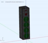
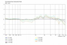
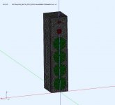
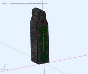
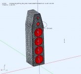
I was running some ABEC simulations on different cabinet features that can effect the MF+HF diffraction as seen in the horizontal polars. I wondering how much design effort this diffraction deserves and the results were interesting. The following sims have only the mid (RS52) dome and tweeter (DC28) dome active with their LR4 BP[725Hz, 4550Hz] and LR4 HP[4550Hz] XOs. The results are normalized to the midrange driver axis at 1m. The woofers are not active and have simple placeholders.
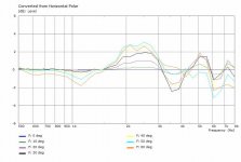
Pic #1+2 are for a flat baffle with no edge rounding. It's what you would expect to see.
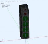
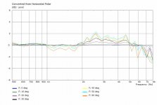
Pic#3+4 are for the same flat baffle with a R20mm roundover on the edges. The improvement is visible on the higher freq since R20 is a modest roundover that's not effective on lower freq.
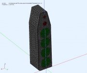
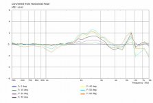
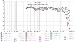
Pic #5+6 are for a trapezoidal shape (13.5deg angle) with R20 roundover edges. This is better, and what I have now, and good considering its a simple shape.
.
I was running some ABEC simulations on different cabinet features that can effect the MF+HF diffraction as seen in the horizontal polars. I wondering how much design effort this diffraction deserves and the results were interesting. The following sims have only the mid (RS52) dome and tweeter (DC28) dome active with their LR4 BP[725Hz, 4550Hz] and LR4 HP[4550Hz] XOs. The results are normalized to the midrange driver axis at 1m. The woofers are not active and have simple placeholders.
Pic #1+2 are for a flat baffle with no edge rounding. It's what you would expect to see.
Pic#3+4 are for the same flat baffle with a R20mm roundover on the edges. The improvement is visible on the higher freq since R20 is a modest roundover that's not effective on lower freq.
Pic #5+6 are for a trapezoidal shape (13.5deg angle) with R20 roundover edges. This is better, and what I have now, and good considering its a simple shape.
.
Attachments
By "...This is better, and what I have now," do you mean "This is better THAN what I have now?"
The trapezoid is better than a flat square baffle. I'm currently using the trapezoid design. I wanted to see if I could make a better baffle, and how much better, so I included the square designs as well. More to come.
MF diffraction#2
Continuing from the earlier MF+HF baffle shapes to reduce diffraction and improve the Hpolar.
Pic#1+2 : The sides are chamferred back to leave a trapezoid face. It's similar to the previous trapezoid.
Pic#3+4 : Cutting in the sides to get more range in baffle width variation. It has multiple edges and might improve with some rounding.
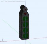
Pic#5+6 : Rounding improves everything and it's very good in the midrange.
.
Continuing from the earlier MF+HF baffle shapes to reduce diffraction and improve the Hpolar.
Pic#1+2 : The sides are chamferred back to leave a trapezoid face. It's similar to the previous trapezoid.
Pic#3+4 : Cutting in the sides to get more range in baffle width variation. It has multiple edges and might improve with some rounding.
Pic#5+6 : Rounding improves everything and it's very good in the midrange.
.
Attachments

Last edited:
Interestingly. The first time I saw the IR for a passive LR4 , I spent at least a week (with DIYaudio help) trying to determine what was wrong with it. It turned out it was suppose to look like that by design. I even measured 4 different commercial speakers that I own (and like) and all of them had very messy IR and steps.
Hi Don,
Very nice thread - I like all the experiments and the modular approach to the speaker.
The messy IR of conventional XO’s is sort of what made me work towards either 1st order transient perfect or the Harsch XO, which I recently managed to do with passively with simple components using a high XO point with a waveguide tweeter and a wide bandwidth woofer (PTT6.5).
Simple Passive Harsch XO Using PTT6.5 and RS28F in a Waveguide
Attachments
Thanks, that's always good to hear.
I have read up on the Harsch after seeing it in one of your threads (probably the one you've linked). I implemented it in a DAC with DSP Raspberry Pi with Piano2.1 DAC DSP and Volumio2
I'm currently locked into the analog LR4 right now and I like it. I can fix the IR using RePhase and a convolution overlay. I think if (or when) I start playing with different XO configurations the entire XO would have to be S/W with a octal DAC.
Continuing from the earlier MF+HF baffle shapes to reduce diffraction and improve the Hpolar.
Pic#1+2 : The sides are chamferred back to leave a trapezoid face. It's similar to the previous trapezoid.
Pic#3+4 : Cutting in the sides to get more range in baffle width variation. It has multiple edges and might improve with some rounding.
Pic#5+6 : Rounding improves everything and it's very good in the midrange.
.
I used the double chamfer of the 1st picture for modular towers I built, they measure well. The sides are 1 inch 45 degree chamfers and 30 degree starting from middle of the midrange to the top of the enclosure. It wasn't easy cutting on my table saw. I tried the trapezoid on my 3 way book shelves and it measured so bad that I switched to a rectangle which has some edge refraction but it is better than the trapazoid.
I used the double chamfer of the 1st picture for modular towers I built, they measure well. The sides are 1 inch 45 degree chamfers and 30 degree starting from middle of the midrange to the top of the enclosure. It wasn't easy cutting on my table saw. I tried the trapezoid on my 3 way book shelves and it measured so bad that I switched to a rectangle which has some edge refraction but it is better than the trapazoid.
Do you have a picture of the speaker? and what was your XO?
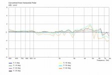
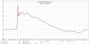
I measured the actual trapezoid design used in the above sim and I get this. Even though I'm happy with it, I plan on making another version (bowling pin) to improve it.
Attachments
Diffraction is a real party poper and I would go far (I did) to mitigate these. The payback is released sound and no or little listening fatigue.
//
LOL😀, that is an extreme case of rounding. Possible overkill, but nicely done.
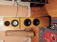
Here is a picture, FR graph and XO.
Here is a link to the Book shelve build.
My lock down project - SB and Fountek 3 way bookshelf
Here is a link to the trapezoidal test.
Baffle step with a trapezoidal baffle
Here is a link to the Book shelve build.
My lock down project - SB and Fountek 3 way bookshelf
Here is a link to the trapezoidal test.
Baffle step with a trapezoidal baffle
Attachments
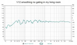
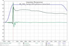
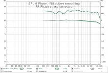
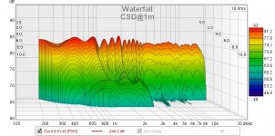
I was wondering how a CSD of the entire speaker would look like at this point. The CSD below is gated to exclude the wall reflections but include the floor reflections. The LF has very little floor bounce due to the quad woofers. The HF has little floor bounce because my carpet starts absorbing it at ~3Khz. The midrange (725->4K5) still has floor bounce that gets attenuated as freq increases. I wonder if I can reduce this further by using a planar midrange ? These are suppose to have more limited vertical dispersion.
The other graphs are for the phase correction to make the LR4 min phase. It improves the IR and STEP but I don't hear much difference. It was used for the CSD.
.
The other graphs are for the phase correction to make the LR4 min phase. It improves the IR and STEP but I don't hear much difference. It was used for the CSD.
.
Attachments
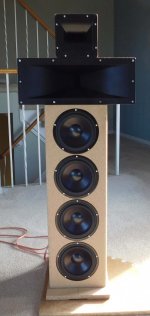
I think I've taken the cone + dome solution as far as I can for now. I like the way they sound. So I'm switching back to the horn solution to compare them.
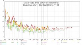
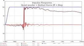
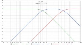
The midrange horn is B52 SH402 + PRV D290 driver that I can get to XO@725Hz with a little EQ. The tweeter is a random ebay slotted + Fane CD130 XO@4550Hz. It was EQ'd flattish and phase corrected to get a cleaner IR + STEP. The THD is about the same as the cone + dome solution. Measurements are @1m midrange height and were gated 1-9ms and FDW15.
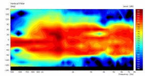
The random ebay slotted tweeter horn creates dip at >40deg off axis, otherwise it's fairly constant up to 18KHz. So I flipped the tweeter 90 deg to get a smoother off axis response at the cost of more off axis attenuation. I can't hear much difference between orientations in the normal sitting position(s). There is a noticeable difference from the domes, the horns seem to have more depth and detail, but I'm not sure why.
.
The midrange horn is B52 SH402 + PRV D290 driver that I can get to XO@725Hz with a little EQ. The tweeter is a random ebay slotted + Fane CD130 XO@4550Hz. It was EQ'd flattish and phase corrected to get a cleaner IR + STEP. The THD is about the same as the cone + dome solution. Measurements are @1m midrange height and were gated 1-9ms and FDW15.
The random ebay slotted tweeter horn creates dip at >40deg off axis, otherwise it's fairly constant up to 18KHz. So I flipped the tweeter 90 deg to get a smoother off axis response at the cost of more off axis attenuation. I can't hear much difference between orientations in the normal sitting position(s). There is a noticeable difference from the domes, the horns seem to have more depth and detail, but I'm not sure why.
.
Attachments
-
 Quad Woofers + HF Horn Flipped Hpolar.jpg112.9 KB · Views: 189
 -
 DSCN8119r.jpg107.1 KB · Views: 172
 -
 Quad woofer + Slotted Horns THD.jpg102.5 KB · Views: 155
 -
 Quad woofer + Slotted Horns IR + Step.jpg69.3 KB · Views: 168
 -
 Quad Woofers + Slotted Horns Hpolar.jpg108.5 KB · Views: 218
 -
 DSCN8120r.jpg115 KB · Views: 210
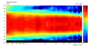
I'm guessing the increased directivity of the horns is your answer. Probably less reflections muddying up the sound. Looking at your last polar it is quite different to that of the dome.
You can see the directivity starting around 600Hz whereas with the dome implementation you last posted, you are not seeing any significant directivity until around 5Khz.
Tony.
You can see the directivity starting around 600Hz whereas with the dome implementation you last posted, you are not seeing any significant directivity until around 5Khz.
Tony.
That's a reasonable explanation. Thanks.
I did an experiment with speakers 2m apart, toed in, listening ~1m in front to swamp the reflections (I think). The effect was still there. Interestingly the wider field domes seem to be more effective at making the speakers "disappear". The horns (90x40deg) have less midrange floor bounce as well which may be a contributing factor.
I did an experiment with speakers 2m apart, toed in, listening ~1m in front to swamp the reflections (I think). The effect was still there. Interestingly the wider field domes seem to be more effective at making the speakers "disappear". The horns (90x40deg) have less midrange floor bounce as well which may be a contributing factor.
Last edited:
crossover effects on polar plots
These are some ABEC sims to look at polars and see if they can be improved by changing the crossover. Starting with the dome + cone variant.
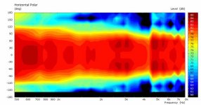
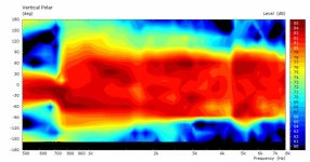
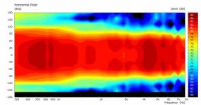
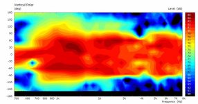
This is for the current LR4 IIR filters. The plots are at midrange height +/-180deg at 3m in 4pi space. The horizontal polar is consistent with wht I've measured. The vertical polar is a bit choppy with holes from the driver overlap and interference.
.
These are some ABEC sims to look at polars and see if they can be improved by changing the crossover. Starting with the dome + cone variant.
This is for the current LR4 IIR filters. The plots are at midrange height +/-180deg at 3m in 4pi space. The horizontal polar is consistent with wht I've measured. The vertical polar is a bit choppy with holes from the driver overlap and interference.
.
Attachments
alt crossovers
The first 3 plots are an attempt to reduce the overlap using a brickwall filter generated by RePhase using 1K tap FIR. The overlap is greatly reduced in the MF-HF, but the abrupt change also exposes the difference in driver beamwidth as the XO blending is removed. Wonder what it would sound like?
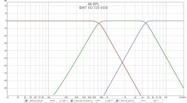
The next 3 plots are reduced overlap, using odd order BW7 filter to shift the lobes, and a 20us tweeter delay to help fill remaining holes. I looks better. Interesting enough to maybe get an octal DAC to try it out.
Any other suggestion that may have worked ?
.
The first 3 plots are an attempt to reduce the overlap using a brickwall filter generated by RePhase using 1K tap FIR. The overlap is greatly reduced in the MF-HF, but the abrupt change also exposes the difference in driver beamwidth as the XO blending is removed. Wonder what it would sound like?
The next 3 plots are reduced overlap, using odd order BW7 filter to shift the lobes, and a 20us tweeter delay to help fill remaining holes. I looks better. Interesting enough to maybe get an octal DAC to try it out.
Any other suggestion that may have worked ?
.
Attachments
-
 Brickwall Filters - RePhase 1K tap.jpg150.6 KB · Views: 124
 -
 Hpolar-Brickwall-Midheight-eq@3m.jpg34.7 KB · Views: 114
 -
 Vpolar-Brickwall-Midheight-eq@3m.jpg36.7 KB · Views: 128
 -
 BW7 XO 725 4550.jpg140.5 KB · Views: 118
 -
 Hpolar-Midheight-BW7-eq-min@3m.jpg33.6 KB · Views: 122
 -
 Vpolar-Midheight-BW7-eq-min@3m.jpg36.9 KB · Views: 114
Last edited:
Interesting, those polars for the brick wall filter may show why people object to them! 🙂
Tony.
Tony.
How come highest spl happens at 30-60 deg off-axis with the brickwall version?
I think it's because there is some diffraction boost. It's also possible to move into the next color by being slightly more than the threshold boundary (3 dB steps in this graph). Could also be cause small changes in EQ between filters.
- Home
- Loudspeakers
- Multi-Way
- Modular active 3 way - work in progress