upgraded quad woofers
I like the quad woofer arrangement and decided to get some better woofers (DSA175).
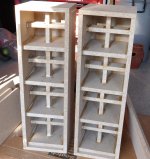
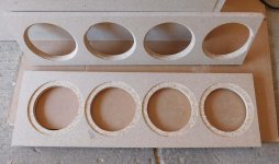
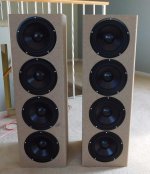
The cabinet pics are attached. The baffle and bottom are 4cm thick (2 layers) and rest is 2cm thick. The side and internal panels are braced mid panel. The drivers are recessed to sit flush on the front with a R20mm side edge roundover. The baffle rear has been chamferred to let the driver breath. Each chamber has a net 6L volume for Qtc=0.6. They will be painted after I decide on the grill, feet (outrigger) and any changes from testing.
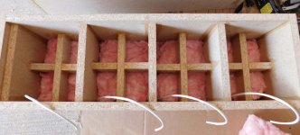
The rear chamber has 120g fiberglass fill per chamber up to the braces (9cm deep, 2.8L). This is 3 layers of ~R7 insulation (2inch nominal) so its compressed a little. This should provide resistivity of ~20K rayls /m over 9cm to suppress any reflections from the rear panel (according to the Hornresp model).
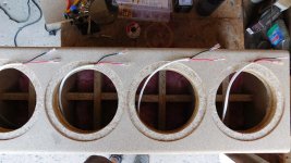
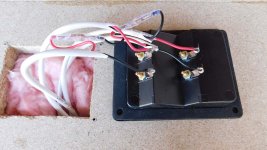
All drivers are wired up to a bi-amp terminal cup. There are 2 drivers in each series chain and each chain is connected in parallel via the terminal straps. There is also a series link to allow disconnecting the series connections to get access to each driver when the terminal cup is removed. I plan on testing all drivers separately and then together.
A quick listen and first impression is they sound very good.
.
I like the quad woofer arrangement and decided to get some better woofers (DSA175).
The cabinet pics are attached. The baffle and bottom are 4cm thick (2 layers) and rest is 2cm thick. The side and internal panels are braced mid panel. The drivers are recessed to sit flush on the front with a R20mm side edge roundover. The baffle rear has been chamferred to let the driver breath. Each chamber has a net 6L volume for Qtc=0.6. They will be painted after I decide on the grill, feet (outrigger) and any changes from testing.
The rear chamber has 120g fiberglass fill per chamber up to the braces (9cm deep, 2.8L). This is 3 layers of ~R7 insulation (2inch nominal) so its compressed a little. This should provide resistivity of ~20K rayls /m over 9cm to suppress any reflections from the rear panel (according to the Hornresp model).
All drivers are wired up to a bi-amp terminal cup. There are 2 drivers in each series chain and each chain is connected in parallel via the terminal straps. There is also a series link to allow disconnecting the series connections to get access to each driver when the terminal cup is removed. I plan on testing all drivers separately and then together.
A quick listen and first impression is they sound very good.
.
Attachments
impedance and THD for DSA175
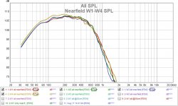
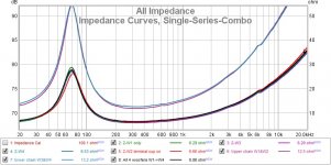
The impedance curves for each woofer, series chain, and parallel chains were measured. This gives a good indication of any air leaks and consistency in the stuffing. All the woofers measure very similar and there is some minor impedance variation for woofer W2 (red curve) which has the wires for all 4 woofers and the terminal cup. The overall impedance curve (black) for all 4 woofers appears to be like a single woofer. Relief 😀
The SPL nearfield was measured (no EQ, with LR4@725Hz) for all 4 woofers. Woofer W4 is closest to the floor and sees some minor deviation from W1-W3. These woofers can go lower than the previous ones so I also moved my sub XO down to 65Hz.
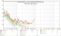
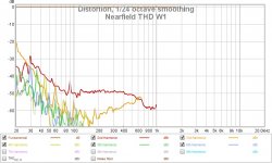
The THD for this woofer is also very low. There are THD curves for nearfield and 30cm. They are all similar so I only posted for W1. They sound good and I've run them at 100dBc @1m and they still sound clean. Another relief 😀
.
The impedance curves for each woofer, series chain, and parallel chains were measured. This gives a good indication of any air leaks and consistency in the stuffing. All the woofers measure very similar and there is some minor impedance variation for woofer W2 (red curve) which has the wires for all 4 woofers and the terminal cup. The overall impedance curve (black) for all 4 woofers appears to be like a single woofer. Relief 😀
The SPL nearfield was measured (no EQ, with LR4@725Hz) for all 4 woofers. Woofer W4 is closest to the floor and sees some minor deviation from W1-W3. These woofers can go lower than the previous ones so I also moved my sub XO down to 65Hz.
The THD for this woofer is also very low. There are THD curves for nearfield and 30cm. They are all similar so I only posted for W1. They sound good and I've run them at 100dBc @1m and they still sound clean. Another relief 😀
.
Attachments
Last edited:
Did you take a free air impedance measurement of the bare driver to compare to the in cabinet ones?
No, but it would be easy to do.
What kind of free air driver mount (OB, no baffle) ? What would I be looking for when comparing the two impedances ?
What kind of free air driver mount (OB, no baffle) ? What would I be looking for when comparing the two impedances ?
Last edited:
I just put it facing up on a solid surface with a cork mat underneath no mount or baffle. That will show you what issues in the impedance are inherent to the driver and which ones are added or possibly smoothed by the cabinet. The closer the cabinet impedance is to the free air one helps to know if you need to do more work on the cabinet or not 🙂
I can get the free air resonance (38Hz) from the datasheet. Let's assume it's correct for a thought experiment.
The free air resonance will be lower (than a closed box <Vas) but so will the Q (0.29). The box reduces the air space (compliance), the resonance frequency increases and the Q increases to where I want it (Qtc=0.6).
If I add more fill, it reduces the air (Q increases) and adds more damping (losses, so Q peak decreases) and resonant frequency increases. The impedance peak will mirror the resonant frequency. Overall the box may appear larger from a combination of effects. What are we trying to achieve ? Why do I want to replicate free air resonance and its impedance peak ?
Last edited:
I must have explained it badly, it is not the peak that is the part to compare but what comes after. As you say the peak will change based on the box configuration. Look at all the other wiggles in the free air curve lots of manufacturers smooth their data which hides the blips. They are resonances or mechanical issues in the driver and will likely remain no matter what the cabinet does. Anything else that shows up in the driver in box measurement is now from the cabinet and by changing the damping, bracing or materials it could be eliminated.
That will help to track down and eliminate cabinet related issues if you want to build the best box you can.
That will help to track down and eliminate cabinet related issues if you want to build the best box you can.
OK thanks for the clarification, that makes sense, I get it. You want to verify the base driver is well behaved or at least find any wiggles. I'm not sure how much of any cone or basket issues will be reflected in the impedance measurement. Fixing the driver to a cabinet will certainly change the resonances (wiggles) as well. New ones might be attributed to the cabinet. I am curious and I have some surplus budget woofers that should have issues, otherwise maybe I'll create some 🙂
I'll give it a try to see what I find.
I'll give it a try to see what I find.
Last edited:
Yes more of a cross check of what you started with Vs what you ended up with. Most of the frequency response issues can be traced back to the impedance. If there are virtually no wiggles the driver is outstanding or the measurement is no good or zoomed out too far 🙂
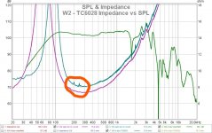
impedance and SPL comparison
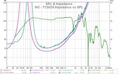
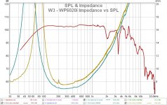
I ran a few experiments to see what issues I could detect from the impedance curves. I used my previous quad test box that used TC6028 and WP6020i woofers. I thought these were more likely to have more types of issues.
Three curves show free air impedance, closed box impedance and the closed box nearfield SPL. I've shifted the closed box impedance curve to make it easier to see. There was no EQ, no XO and SPL was gated 30ms.
Some (but not all) of the SPL variations can be seen in the impedance curves. This was a quick test box so there is some "fuzziness" in the closed box impedance curve (vibrations?). The impedance peak is always clear and useful to determine box tuning but the other issues are not so obvious. I think it would be easier to just use the SPL curves to find issues.
Attachments
Last edited:
The impedance peak is always clear and useful to determine box tuning but the other issues are not so obvious. I think it would be easier to just use the SPL curves to find issues.
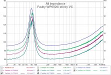
I've put a circle around the areas that are visibly different to me. Those blips represent resonances of some type and the fact that they are not visible in the near field response is why I think the impedance graph is useful. They would appear somewhere in the impulse response but filtering and messing about trying to find them is a lot of effort when you can see them right there in the impedance response.
They are cabinet related and likely appear later in time or from off axis angles and are in the hard to measure accurately at home range. By trying different stuffing arrangements you can see if these disappear or get smaller.
They are not huge by any standard but they look like the ones I had from a bare box without stuffing.
Full Range TC9 Line Array CNC Cabinet
Post#191 in my array thread is where I show the impedance measurements for the different stuffing schemes. Quite a few images and graphs so I won't repost them here.
Attachments
OK, that's more specific, thanks. That test cabinet was a quick build and I'm not surprised it has some resonances/vibrations. You can also see that in the "fuzzy" closed box impedance line.
Thanks for the link to your LA material stuffing trials. A very good read.
You might find this interesting. One of my budget woofers (WP6020i) had unusual voice coil friction. It was initially enough to hear the difference from its peer and easily see it in the THD measurements. It got much better with some accelerated burn in but the issue still shows up in the impedance curve. It's not consistent (probably dirt shifting), and "can" get smoother with higher drive levels. It's more extreme, and less repeatable than your measurement anomaly. The curves have been shifted to make it easier to see.
.
Attachments
Last edited:
Hi Don, if you haven't seen it, this is definitely worth a read Testing Loudspeakers: Which Measurements Matter, Part 2 | audioXpress part 1 too. I've linked part2 specifically for the info it has on impedance measurements.
Tony.
Tony.
Thanks for the link Tony. Very interesting and I read both parts.
The part on impedance measurements are in line with what @fluid was saying.
The part on dynamic compression likely describes the problem I was having with the previous woofers (tc6028, wp6020i). I don't get that "muddy" sound problem with the new woofers but then I also changed some other thing to try and avoid it (stiffer construction, denser damping material).
I bought the D'apolito book "testing loudspeakers" ages ago. I really should re-read it. Lots of useful info 🙂 I should re-read those two articles as well!
Tony.
Tony.
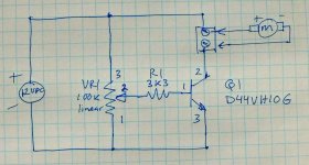
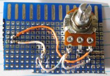
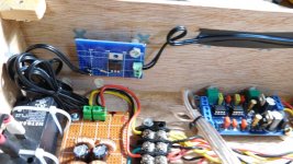
A small simple addition to control the cross air fan speed on my XO and Amp boxes.
Approx $2 in parts for analog fan speed control from 0->100%. The speed is set low and you have to put your ear beside the box to actually hear them.
The amp box has qty 4 T-amp boards that use 7W each on idle. So very little air is needed to move the heat, and the exhaust air is barely warm.
Approx $2 in parts for analog fan speed control from 0->100%. The speed is set low and you have to put your ear beside the box to actually hear them.
The amp box has qty 4 T-amp boards that use 7W each on idle. So very little air is needed to move the heat, and the exhaust air is barely warm.
Attachments

Nice! I never thought of doing something like that for my PC with noisy fans! Not enough speed control ports on the motherboard, I guess if you wanted to get really tricky you could use a temp sensor as well (not necessary for your application I would think).
Tony.
Tony.
Heat is not really a problem so I can use a fixed rate. The power supply(s) don't have any fans so they also should (old habit 🙂 ) have some air cooling. The T-amp boards also have a thermal sensor and fan control but it's binary on/off control and I don't like the sound of small high speed fans so I have a bigger, slower, quieter fan.
DonVK Did you like the LR4 more than the LR2? My experience it that LR4 gives a deeper soundstage and LR2 A bigger (wider).
Have you tried the 2" driver with a wider baffle or is it blending good? I noticed they can get a little hard on rock with to slim baffles (tower design).
Have you tried the 2" driver with a wider baffle or is it blending good? I noticed they can get a little hard on rock with to slim baffles (tower design).
I've only tried LR4 for this speaker project because the XO is fixed active analog. I like the way it sounds and measures. At some point I'll probably do a S/W XO and then everything is possible.
The polar for the current setup (different woofers) is at Modular active 3 way - work in progress and it's blends fairly good. I'll be modifying the MF+HF baffle to get the polar a little smoother. I've tried a few different baffle shapes that are also posted earlier in this thread.
The 2" Al dome has very good seperation, detail and low distortion but it can sound stark or harsh on some music. I have not noticed any acoustic change from different baffle shapes but then they were all narrow as I attempted to change the diffraction pattern and improve the polar.
- Home
- Loudspeakers
- Multi-Way
- Modular active 3 way - work in progress