There is a lot of information here from Gaga and others, chrome can translate it as you go and it is still understandable for those that don't read german
Der ABEC Thread...
Der ABEC Thread...
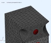
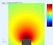
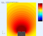
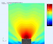
The sides were scalloped out, to reduce the baffle width. Its helps, but the wavefront starts to deform at 3Khz and there is some scattering by 4.5Khz. It think it could benefit from more rounding at the corners and a longer (Z>14cm) scallop. This was a simple cylindrical cut through the edges with some roundover. It's better than a flat baffle <2Khz but choppier above 2Khz.
.
.
Attachments

Last edited:
In my mind I was thinking that you might use the scallop across all three drivers centered on the mid by taking out some of the baffle near the tweeter and woofer. I realise that this is a much longer sim but I think the result would be better.
A longer scallop would provide a smoother transition but would also interfere with a desire to make the speaker modular so I can swap parts. The scallop is not required for the woofers or other potential midrange solutions (cones or horns). So its preferred to have a localized solution.
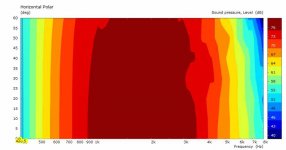
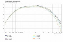
The midrange sims were used to see how much dome related variation was inherent in the cabinet and whether it could be further reduced.
The midrange sims were used to see how much dome related variation was inherent in the cabinet and whether it could be further reduced.
Attachments
Last edited:
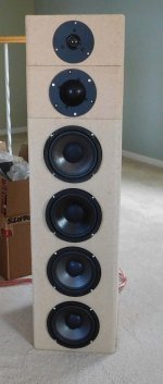
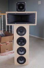
On to some more listening with the quad woofers setup and MF/HF horns replacing the domes.
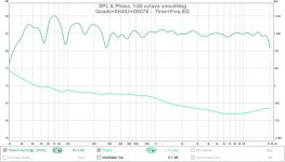
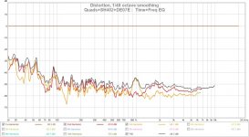
It is much more effort to get everything aligned because the driver coil positions vary so much due to the horn length differences. The horns are moved to time align the drivers and eliminate the MF and HF nulls. Then a bunch of EQ was applied to flattened the FR@1m until I have something that measures like the dome solution. A single BP6 sub (80Hz) is used and there are some LF room issues (nulls) showing up.
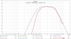
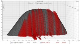
I should add that my MF driver PRV290py-B does not go low enough to cross properly at 725Hz. The SH402 horn is suppose to load to 400Hz so I think it's driver limited. I can EQ the FR flat but the intended lower MF slope (LR4) is not correct. I added a midrange CSD and FR graph to show where it falls short. The HF horn has no problems.
It is much more effort to get everything aligned because the driver coil positions vary so much due to the horn length differences. The horns are moved to time align the drivers and eliminate the MF and HF nulls. Then a bunch of EQ was applied to flattened the FR@1m until I have something that measures like the dome solution. A single BP6 sub (80Hz) is used and there are some LF room issues (nulls) showing up.
I should add that my MF driver PRV290py-B does not go low enough to cross properly at 725Hz. The SH402 horn is suppose to load to 400Hz so I think it's driver limited. I can EQ the FR flat but the intended lower MF slope (LR4) is not correct. I added a midrange CSD and FR graph to show where it falls short. The HF horn has no problems.
Attachments

Nice project.
Off-topic perhaps, but can you explain how did you generate the target curve in REW (post #205, third graph)?
Off-topic perhaps, but can you explain how did you generate the target curve in REW (post #205, third graph)?
Almost certain he did it with rephase, choose the filters you want and export to 32 bit float wav and import into REW.
 that's exactly how the template (ideal curve) was created
 Complements with your project, very nicely executed process and a joy to read!
Thanks, that's good to hear.
pressure response vs power response
These trial systems were EQ'd to have approx the same axial response (ie. SPL@1m). The directivity is not the same so the power response of these speakers is also not the same. All the acoustic power emitted is in the room and should effect the sound.
So it should be possible to derive the power response using the pressure response and polar curves. Does anyone actually do that ??? is there a s/w tool ?
Thanks Don & Fluid. I thought (wrongly) there was a way to generate it in REW without importing.
I use a 3/4" (19mm) roundover as the default roundover on my boxes. I model this as a R20mm roundover because I like to round up 🙂.
Hello Don,
You asked: So it should be possible to derive the power response using the pressure response and polar curves. Does anyone actually do that ??? is there a s/w tool ?
That is what Vituixcad was designed for. There is a separate window for DI and Power response. Additionally "heatmaps" can be displayed.
That's good to know that VituixCad can do these predictions. Thanks.
What about measuring the power response from an actual speaker. ?
What about measuring the power response from an actual speaker. ?
Isn't the Power Response calculated from SPL measurements in all angles, and thus not directly measurable?
I think its the SPL integrated over the radiated surface area (so the directivity counts). I thought I read once that it could be estimated using only several measurements at different angles/distances. Still trying to find that. It would be even better if a tool did the calc for me.
I think you are looking for the ANSI / CTA 2034 standard aka "spinorama" this will show you how the different standard responses such as early reflections and power response are generated.
True power response is quite an effort to measure. Early reflections is the closest to how a speaker will measure in a room above transition.
Copy attached
True power response is quite an effort to measure. Early reflections is the closest to how a speaker will measure in a room above transition.
Copy attached
Attachments
- Home
- Loudspeakers
- Multi-Way
- Modular active 3 way - work in progress