You might be interested in making one or for small signal transistors buying an Atlas DCA75 Pro USB Tester....
Interesting. I do have a DCA75 Pro. I'll have to see if I can get the software running under Wine or something (I'm a Mac user).
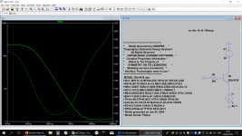
2N3058 PSpice model: current gain vs frequency at 1A emitter current and 30V Vcb.
Attachments
Last edited:
2N3058 PSpice model: current gain vs frequency at 1A emitter current and 30V Vcb.
That's i think around 25 MHz at 0dB. Not bad for a TO-3.
It's just a model. Accuracy is questionable.That's i think around 25 MHz at 0dB. Not bad for a TO-3.
The ft varies with current and voltage too, of course.
I'm thinking the rumours of 2N5038 having an ft of 60MHz are exaggerated. It may even be a typo that keeps getting copied. I see no mention of ft in the On-Semi datasheet. 6MHz is more believable.
If you extrapolate the gain slope in my previous post until it crosses the gain=1 axis you get about 5 or 6MHz ft.
This seems more reasonable because it is a very old transistor. A dinosaur.
If you extrapolate the gain slope in my previous post until it crosses the gain=1 axis you get about 5 or 6MHz ft.
This seems more reasonable because it is a very old transistor. A dinosaur.
I think 25 MHz is not too good to be true. I was expecting something like 28 MHz. I think the datasheet is believable. With Ic=2A, 5 MHz signal has hfe=12. It means with typical first order roll off, at hfe=1 or at 0 dB the bandwidth is 60M. But that's at 2A where many other transistors are measured at 0.5A. This is a high current transistor and when hfe is not linear we will find very low hfe at very low current.
With fT=25M the gain with 5M test signal will be around 5x. This is with lower current than 2A. This is still slower than MJW4281.
With fT=25M the gain with 5M test signal will be around 5x. This is with lower current than 2A. This is still slower than MJW4281.
Last edited:
2N5038
With Vce=10V, Ic=2A I get a gain of 1.7 at 5Mhz using the PSpice model.
If I crank up the current to 12A I get a dc gain of 37 (agrees with the datasheet: above the min of 20) and an ft between 10 and 20MHz.
Things get a lot worse as Ic drops to Naim bias current levels: about 200kHz at 30mA and 30V.
I think you're right. Within that 2N5038 model, TF=1E-8 or 10E-9. Cordell's shows TF=2.7E-9 for MJW4281. Thats 4 times faster. So if MJW4281 is 30M, 4 times slower is around 7.5M, similar to your calculation.
TF is maximum value from 1/(2*pi*fT), in pico second.
BTW, if 2N5038 is much faster than the standard NAP transistor, it cannot be used in the same circuit without changing the compensation.
If the estimates are correct, then it's in the same ballpark as some of the
factory NAP output transistors (BDY58 10MHz, BUV20 8Mhz).
factory NAP output transistors (BDY58 10MHz, BUV20 8Mhz).
If the estimates are correct, then it's in the same ballpark as some of the
factory NAP output transistors (BDY58 10MHz, BUV20 8Mhz).
Plus it is in a metal case and available. A funny thing though I have a simulation using Cordell .models for this amplifier including the MJL3281.
I am aware there are doubts about the accuracy of MODPEX .models and I am not reading too much into the observations I made when 2N5038 is substituted for MJL3281.
The fT specification for MJL3281 is 30 MHz - although this measure peaks somewhere between 50 and 60 MHz at 3A.
Anyway the swap results in a 12dB increase in gain at 1Hz and the unity gain point is reached at double the frequency as for MJL3281.
On the other hand the - 3dB frequency point falls to about half than that for MJL3281 so the compensation would have to be changed and this does not make for a straight forward substitution.
Seeing all this makes me wonder about BUV20 used in the NCC200 module the IC rating is high and the fT looks fine on paper but there is no .model for this. There is no output limiter in the module and that could be the first reason above all for selecting it.
The BUV20 is also the clear winner at keeping itself cool (0.7ºC/W, vs. 1.0ºC/W for the BDY58 and 1.25ºC/W for the 2N5038).
Although that's no doubt predicated on the BUV20's two dies sharing the load, which might be questionable at a peak Ic of ~8A. Judging from the knee in the SOA curve I'm guessing they're 50:50 above 10.5A, so we're not far off.
(FWIW, in my sims dropping the R in the feedback RC to 1K keeps the 2N5038 from oscillating.)
Vereker was not a fan of paralleling power transistors nor complementary ones. Unlike the American environment destroyers like Krell who used a whole load of transistors in class A. I think the old KSA-50 may have used MJ15024/25 pairs which are pretty decent transistors in TO-3. Naim went for less beefy transistors and then ran them cool and later had custom die mounts made of copper to help lower the thermal resistance between die and case. It seems their new transistors for The Statement use twin dies and complements - so JV's rules broken.
I still haven't heard The Statement. I've heard their top-end 500 series system through Focal speakers. Pretty impressive. A touch lively for my taste. You know the feeling you get in your ears at an airport if you are outside while a jet taxis by...that sort of shrill, drilling white noise. Well after the plane is gone your ears retain an impression of the engine whine. That's what the Naim system left me with. Exciting though.
I also heard my first Class D amplifier through Wilson speakers last weekend. Very interesting sound - unexpectedly clear mids but somehow exaggerated and unnatural, lacking PRaT, recessive bass and treble. I might tire of it after a while.
Here's a teasy question for the ponderer: what is the ft of a class D amp?
Member
Joined 2009
Paid Member
Let's face it, us clone builders, we are engaged in industrial archeology. There's no expectation that NAIM would stick with the old approach except where it suits them.
Now, watching and listening to an English Electric Lightning take off and climb vertically to 5,000ft in no time at all - that's exciting !!!!
YouTube
Now, watching and listening to an English Electric Lightning take off and climb vertically to 5,000ft in no time at all - that's exciting !!!!
YouTube
Attachments

Last edited:
The BUV20 is also the clear winner at keeping itself cool (0.7ºC/W, vs. 1.0ºC/W for the BDY58 and 1.25ºC/W for the 2N5038).
Although that's no doubt predicated on the BUV20's two dies sharing the load, which might be questionable at a peak Ic of ~8A. Judging from the knee in the SOA curve I'm guessing they're 50:50 above 10.5A, so we're not far off.
(FWIW, in my sims dropping the R in the feedback RC to 1K keeps the 2N5038 from oscillating.)
I could not see any mention of two dies in any of the datasheets. There was a term multiepitaxial transistor. See US5034337A - Method of making an integrated circuit that combines multi-epitaxial power transistors with logic/analog devices
- Google Patents
A succinct observation of what many of us are doing here, even with new designs. I'm sure its a nostalgia thing that has to do with preservation - making museum replicas of iconic commercial products as much as building and enjoying working amplifiers with similar performance.....us clone builders, we are engaged in industrial archeology...
... making museum replicas of iconic commercial products ....
Indeed. I'm even soldering leads on a surface-mount naked staked film cap to get the right look of the Zobel capacitor.
Of course I'm doing my own two-layer boards, so contradictions abound. 🙄
BTW: that brings me to another question: has anyone found a trimpot that resembles the original ones Naim used?
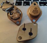
It looks like a wild animal chewed the lid off! How did you even do this?Pardon my frightful job at opening the case:
Try a hacksaw next time. 😀
- Status
- Not open for further replies.
- Home
- Amplifiers
- Solid State
- Modified Naim NAP140 Schematic