This type of circuit inverts the signal so the voltage drop across R11 will register as negative in phase. The divider network provides a suitable nfb connection from the collector to the base.
I broke the NFB loop in a couple of places and injected an AC signal; while R11 does change the phase margins, it doesn't do anything dramatic until a couple of MHz, and even there it's making the phase margin worse rather than better (not that it's likely to make any difference as the loop gain at that point is 16dB under unity).
I broke the NFB loop in a couple of places and injected an AC signal; while R11 does change the phase margins, it doesn't do anything dramatic until a couple of MHz, and even there it's making the phase margin worse rather than better (not that it's likely to make any difference as the loop gain at that point is 16dB under unity).
Julian Vereker investigated power transistors for switching applications these are a different breed from MJ15003 which has a Gain Product Bandwidth of one at 2MHz which is the element of frequency bandwidth the other being closed loop gain.
Let me try another line of thinking.
The normal bias spread is about 2.1V, with 0.2V over the 27R and 1.9V over the Vbe multiplier. That gives us about 3Vbe of tempco.
If everything really reaches the same temp inside the case, then that's about right (2Vbe for the EF and 1Vbe for the CFP).
If we don't have the 27R, then we're looking at more like 3.5Vbe of tempco. That might work better at start-up, but will overcompensate if everything really does reach thermal equilibrium.
I expect the output stage needs 2.3V or so of bias voltage. The upper darlington has two BE junction drops and the lower pseudo-darlington has one BE drop and a diode drop. The power transistor emitter resistors will only drop about 6mV each at idle.
Last edited:
Let me try another line of thinking.
The normal bias spread is about 2.1V, with 0.2V over the 27R and 1.9V over the Vbe multiplier. That gives us about 3Vbe of tempco.
If everything really reaches the same temp inside the case, then that's about right (2Vbe for the EF and 1Vbe for the CFP).
If we don't have the 27R, then we're looking at more like 3.5Vbe of tempco. That might work better at start-up, but will overcompensate if everything really does reach thermal equilibrium.
Naim owners manuals recommend their should be plugged in and not turned off.
I once attended a Naim demonstration given by Julian Vereker and hosted by the local Hi-Fi Naim outlet many years ago.
The equipment used was not from the stocks of the outlet and the show did not start until the new amplifier Vereker had brought along had been powered up and fully warmed up.
This process was given his full care and attention and it took a long time before he was ready - the reason why I remember this is that I liked to be punctual and did not like delays and lateness. Fortunately now with age and more time on my hands I can afford to be more relaxed and patient.
I was once at a demo given by JV where all audience members were asked to leave their digital watches in another room. This was before people all had mobile phones.
I expect the output stage needs 2.3V or so of bias voltage. The upper darlington has two BE junction drops and the lower pseudo-darlington has one BE drop and a diode drop. The power transistor emitter resistors will only drop about 6mV each at idle.
Yes, it's 2.4V. I forgot to reset the bias after changing the Vbe from a 2N5551 to a BC549 (which should be closer to the original ZTX108).
That puts the Vbe multiplier at 3.6X w/27R and 4.0X without. Not much of a difference, and if we really wanted 3Vbe of tempco then we'd want 75R.
Unless JV verified experimentally that with the various Rthermals involved between the output device junctions and the Vbe junction that 3.6Vbe of tempco was appropriate?
I think it would have been better if you had chosen BDV20 devices when you bought your modules but these are no longer in production. Possibly the niche in the market has been taken over by power FET's - I could not find a modern equivalent. I note the latest NCC uses MJ15003/15004 outputs.
Anyway 2N5038 is a device I remember from the 1970's which is still in production and you might consider this as a prospect as a drop-in replacement.
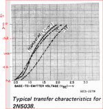
I have an old RCA Power Devices Handbook and the graph of Ic/Vbe is a little unusual and interesting since the best place in a Class AB amplifier for switching is where the plot is flattest and making the distance between sample points as small as possible.
The latter would be aided by reducing the switching times - a specification you get with this device but not with MJ15003.
The graph for 2N5038 is unusual in that it has two steps in the turn on region and at 25 degrees C conduction starts with a Vbe a little less than 500 m.V.
Anyway 2N5038 is a device I remember from the 1970's which is still in production and you might consider this as a prospect as a drop-in replacement.
I have an old RCA Power Devices Handbook and the graph of Ic/Vbe is a little unusual and interesting since the best place in a Class AB amplifier for switching is where the plot is flattest and making the distance between sample points as small as possible.
The latter would be aided by reducing the switching times - a specification you get with this device but not with MJ15003.
The graph for 2N5038 is unusual in that it has two steps in the turn on region and at 25 degrees C conduction starts with a Vbe a little less than 500 m.V.
Attachments
I think it would have been better if you had chosen BDV20 devices when you bought your modules but these are no longer in production....
Was this a reply to me?
I'm not using MJ15003s (except in SPICE because I don't have models for the others).
For my boards I have 10 Siemens BDY58s and 10 Motorola BUV20s. Since it appears that the cheapest way to get a Naim sleeve is to buy an olive series NAC102 or NAP180, I might as well spend a bit more on the 180 and get 4 NA001s and a "proper" transformer.
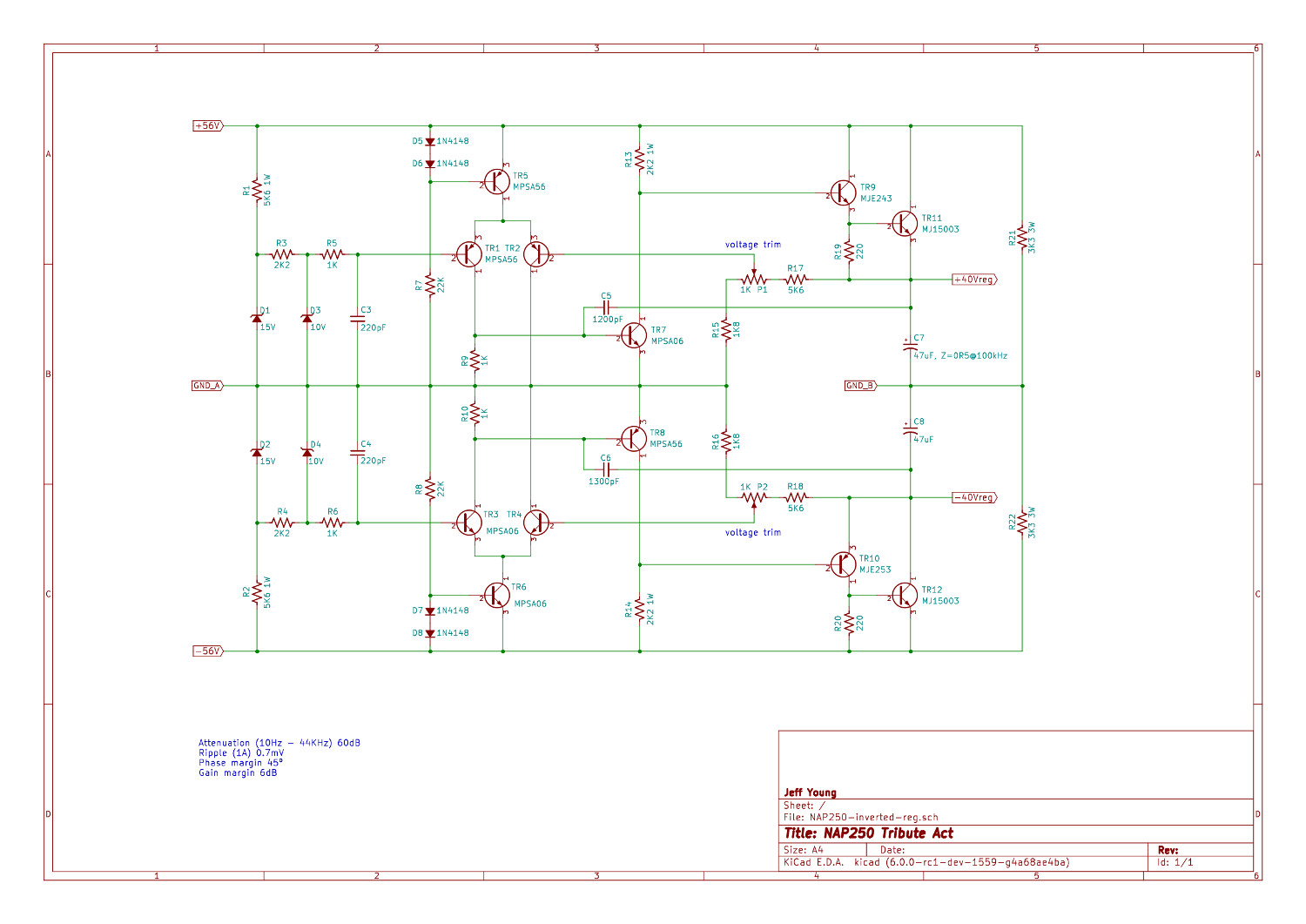
Current plan is to build 2 sets of regulators and 3 sets of amp boards. One set of regulators will be classic NAP250; the other will be with the VAS inverted for a cleaner reference and a CCS for the LTP:
Not sure which regulator set should get BDY58s and which should get BUV20s....
Attachments
Those are not the best transistors for this application.I note the latest NCC uses MJ15003/15004 outputs.
Was this a reply to me?
I'm not using MJ15003s (except in SPICE because I don't have models for the others).
For my boards I have 10 Siemens BDY58s and 10 Motorola BUV20s. Since it appears that the cheapest way to get a Naim sleeve is to buy an olive series NAC102 or NAP180, I might as well spend a bit more on the 180 and get 4 NA001s and a "proper" transformer.
Current plan is to build 2 sets of regulators and 3 sets of amp boards. One set of regulators will be classic NAP250; the other will be with the VAS inverted for a cleaner reference and a CCS for the LTP:
Not sure which regulator set should get BDY58s and which should get BUV20s....
Yes specifically but also to others generally interested. I was concerned that my comment about the Gain Bandwidth Product of MJ 15003 and that it might be your intention to use these. Good for you that is not the case.
I looked for datasheets for the BUV20 and found one from Semelab which is attached.
The BUV20 Gain Bandwidth Product has to exceed 100MHz since the gain at that frequency is 8.
The 2N5038 has a gain of 12 at 5MHz some references extrapolate that to an fT of 60MHz.
The BDY56 or BDY58 were used in Naim amplifiers in the 1970's these have an fT of 10 MHz.
The MJ15003 has an fT of 2MHz ( a gain of one).
You already have ten BUV20's (Motorola) so you could use 4 of these in your present board and if you buy a Nap 180 spend a bit of time doing some listening comparisons before deciding what to do next.
The regulated supplies in the Naim NAP250 had resistors in the raw supply lines with transistors monitoring the voltage drops across these and if the voltage drop was too high in the resistors in either raw the sense resistors would activate a 2 transistor trip arrangement to cut off the supply.
Also there are no load line output short circuit protection transistors in the main amplifier.
I think Naim wanted to minimize the chances of come backs for repairs.
Attachments
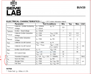
The Motorola BUV20 datasheet (attached) has a bit more data than the Semelab.
I didn't have as much luck with the BDY58. The Comset datasheet (also attached) has a bit more info than the typical Semelab, but not by much.
As for protection circuits, I always delete them, otherwise I'll never have a reason to use all the extra amps I seem to have accumulated. 😀
I didn't have as much luck with the BDY58. The Comset datasheet (also attached) has a bit more info than the typical Semelab, but not by much.
As for protection circuits, I always delete them, otherwise I'll never have a reason to use all the extra amps I seem to have accumulated. 😀
Attachments
The BUV20 Gain Bandwidth Product has to exceed 100MHz since the gain at that frequency is 8.
😕
The Motorola BUV20 datasheet (attached) has a bit more data than the Semelab.
I didn't have as much luck with the BDY58. The Comset datasheet (also attached) has a bit more info than the typical Semelab, but not by much.
As for protection circuits, I always delete them, otherwise I'll never have a reason to use all the extra amps I seem to have accumulated. 😀
The datasheets for 2N5038 and a simulation model is available from On-Semi if you want to examine a higher fT transistor - see Simulation Models: 2N5038
Possibly with BDV20 outputs you may get away without the load line short circuit protection in the amplifier module.
I think it would be good policy to include the trip circuit for the regulated supply - I have built a couple of pairs of these and I know they work the trip is not activated in use but it would be if the output or either of the supply rails is shorted.
The Motorola BUV20 datasheet (attached) has a bit more data than the Semelab.
I didn't have as much luck with the BDY58. The Comset datasheet (also attached) has a bit more info than the typical Semelab, but not by much.
I see you have you have your name on the group buy thread for a Semisouth curve tracer. When you get to use this I hope you will post some test results for these power transistors - particularly the transfer characteristic in the critical turn on region.
Hi Michael,
The group buy is just for the SemiSouth JFETs; Patrick is doing the curve tracing.
On the other hand, a curve tracer would be cool. I'll have to look into that....
Cheers,
Jeff.
The group buy is just for the SemiSouth JFETs; Patrick is doing the curve tracing.
On the other hand, a curve tracer would be cool. I'll have to look into that....
Cheers,
Jeff.
Hi Michael,
The group buy is just for the SemiSouth JFETs; Patrick is doing the curve tracing.
On the other hand, a curve tracer would be cool. I'll have to look into that....
Cheers,
Jeff.
You might be interested in making one or for small signal transistors buying an Atlas DCA75 Pro USB Tester.
A couple interesting threads I have found interesting - see
Intelligent Curve Tracer 3.0 release
Looking for a small signal NPN with no Quasi Saturation: MEASURED DATA
I may have misunderstood the method all along but the Semelab datasheet states that at F=100MHz, Ft is determined to be just 8MHz - i.e. a gain of only 0.08. This is more in line with older BJT power switching devices such as SGS-Thomson's BDY56,58 which followed the original Solitron and apparently other similar switching types when they were dropped due to reliability or supply problems.The BUV20 Gain Bandwidth Product has to exceed 100MHz since the gain at that frequency is 8.........
An Ft of 100MHz for and old-tech power transistor would make it quite an expensive choice, being high in the RF power category. I don't think this was likely in the 1970s or even now.
I may have misunderstood the method all along but the Semelab datasheet states that at F=100MHz, Ft is determined to be just 8MHz - i.e. a gain of only 0.08. This is more in line with older BJT power switching devices such as SGS-Thomson's BDY56,58 which followed the original Solitron and apparently other similar switching types when they were dropped due to reliability or supply problems.
An Ft of 100MHz for and old-tech power transistor would make it quite an expensive choice, being high in the RF power category. I don't think this was likely in the 1970s or even now.
Thanks for point the error out. I was too wrapped up with the 2N5038 datasheet and applied the wrong logic in the case of BUV20.
The 2N5038 is described in Towers 1977 and Motorola Semiconductor Selection Guide and Catalogue 1984 as having a fT of 60 MHz - that is Minimum according to Motorola.
The 2N5038 is described in Towers 1977 and Motorola Semiconductor Selection Guide and Catalogue 1984 as having a fT of 60 MHz - that is Minimum according to Motorola.
In fairness with other transistors, the (60MHz) number seems to be too good to be true. It's minimum hfe is 20 at Ic=10-12A. OTOH, small signal fT measurment is done with Ic=2A with the result of hfe=12. It seems to me that this transistor is not linear. It means, at lower than 2A (which is the current we are interested in) the hfe is lower than that, and so the fT.
So I googled ".MODEL 2N5038" and I found from ONSEMI website the following model:
Code:
**************************************
*      Model Generated by MODPEX     *
*Copyright(c) Symmetry Design Systems*
*         All Rights Reserved        *
*    UNPUBLISHED LICENSED SOFTWARE   *
*   Contains Proprietary Information *
*      Which is The Property of      *
*     SYMMETRY OR ITS LICENSORS      *
*    Modeling services provided by   *
* Interface Technologies [URL="http://www.i-t.com"]www.i-t.com[/URL] *
**************************************
.MODEL Q2n5038 npn
+IS=1.48811e-12 BF=98.2047 NF=0.85 VAF=20.3229
+IKF=9.99719 ISE=2.5e-12 NE=3.5625 BR=2.61957
+NR=1.50997 VAR=11.8008 IKR=8.23854 ISC=9.25e-13
+NC=3.78125 RB=5.80602 IRB=0.1 RBM=0.1
+RE=0.000223855 RC=0.11642 XTB=0.100521 XTI=1.21903
+EG=1.13244 CJE=1e-07 VJE=0.4 MJE=0.85
+TF=1e-08 XTF=6.5813 VTF=7.29946 ITF=0.001
+CJC=5e-10 VJC=0.95 MJC=0.23 XCJC=0.792584
+FC=0.8 CJS=0 VJS=0.75 MJS=0.5
+TR=6.47842e-07 PTF=0 KF=0 AF=1
* Model generated on Jan 24, 2004
* Model format: PSpice- Status
- Not open for further replies.
- Home
- Amplifiers
- Solid State
- Modified Naim NAP140 Schematic